
Electric component for high frequency power amplifier

Inactive Publication Date: 2005-12-22
RENESAS ELECTRONICS CORP +1
View PDF2 Cites 73 Cited by
  • Summary
  • Abstract
  • Description
  • Claims
  • Application Information

AI Technical Summary

Benefits of technology

[0008] In the field of cellular phones, a request to make electric components configuring a system smaller is high in order to reduce the body in size. An electric component for high frequency power amplifier (hereinafter, called an RF power module) incorporating a high frequency power amplifier amplifying and outputting a transmitting signal and a power source circuit supplying operating voltage is not exceptional. To achieve making the module smaller, it is important to miniaturize ICs (semiconductor integrated circuits) and components such as devices constituting the module and to reduce the space between the components. As the space between the components is reduced, the temperature in the module is higher due to heat generated by the components.

Problems solved by technology

The provision of such fins increases the size of the module, obstructing making a cellular phone equipped with the same smaller.

Method used


Image

  • Electric component for high frequency power amplifier
  • Electric component for high frequency power amplifier
  • Electric component for high frequency power amplifier

Examples


Embodiment Construction

[0031] A preferred embodiment of the present invention will be described below based on the drawings.

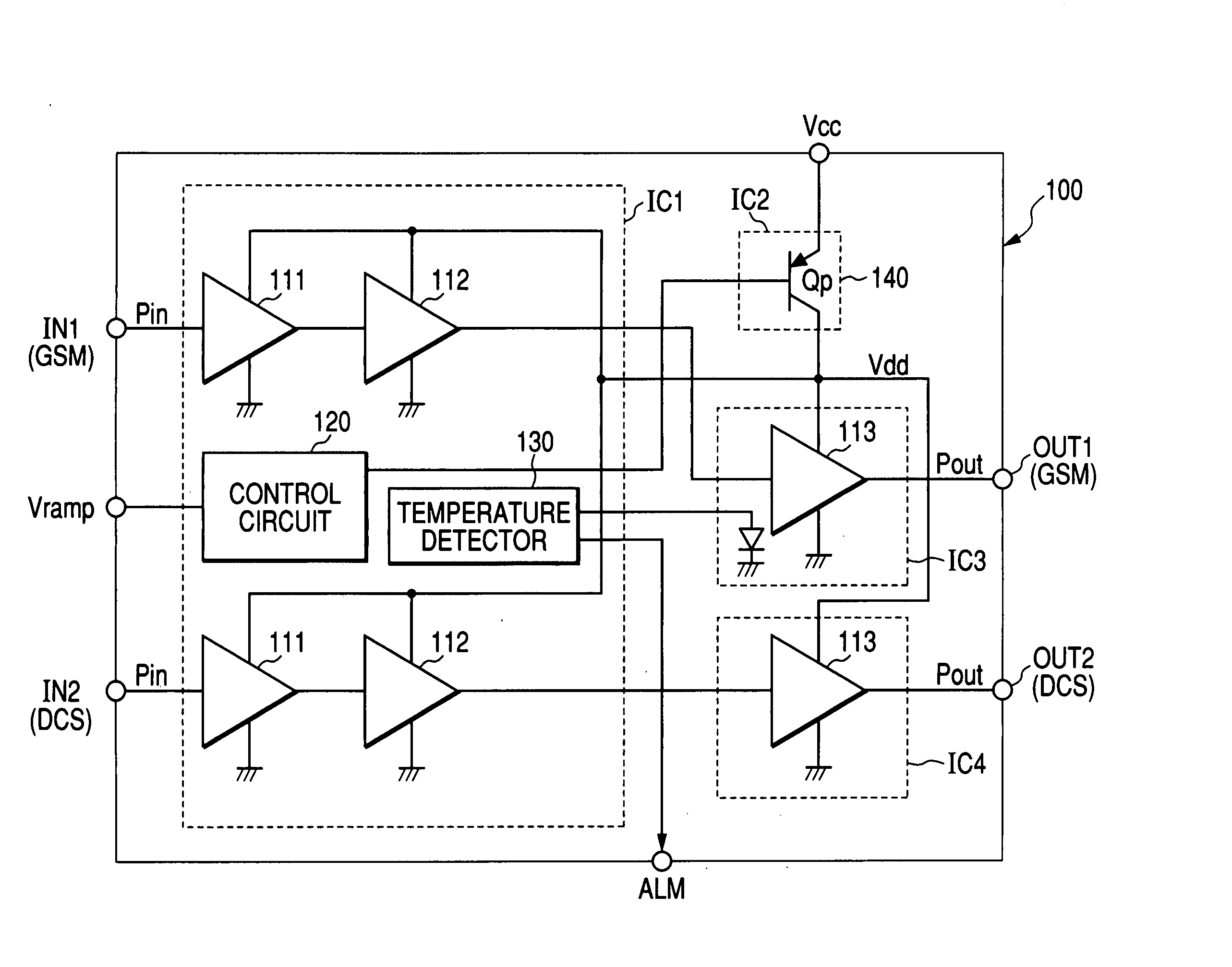
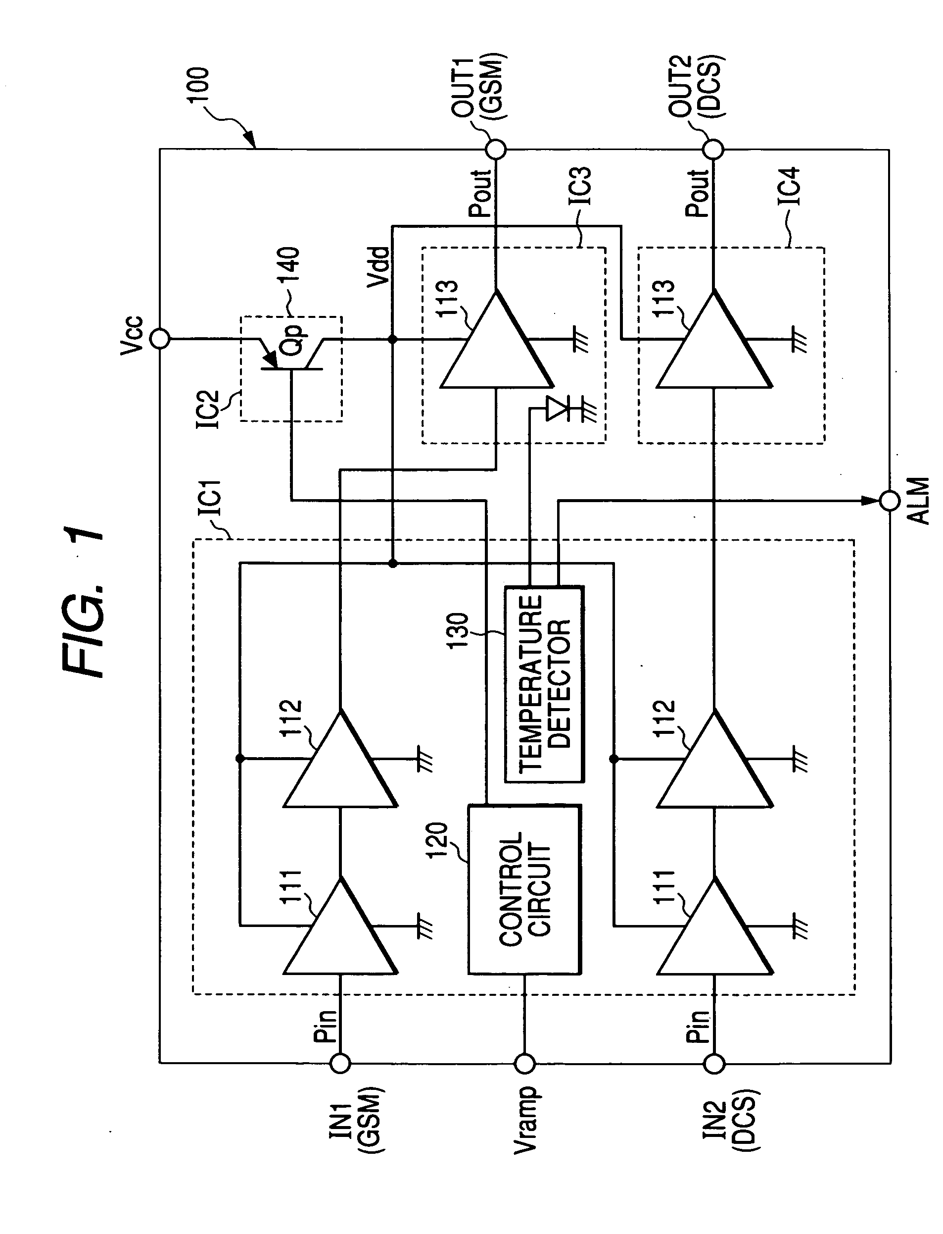
[0032]FIG. 1 shows an embodiment of an RF power module having a temperature detector according to the present invention. In this specification, a module is handled as one electric component in such a manner that plural semiconductor chips and discrete components are mounted over an insulator substrate such as a ceramic substrate provided with printed wiring over its surface and inside so that the components are connected by the printed wiring or bonding wires to play a predetermined role.

[0033] Not being particularly limited, an RF power module 100 according to this embodiment is constructed as a module which can amplify a transmitting signal in the frequency bandwidth of two communication systems of GSM (Global System for Mobile Communication) and DCS (Digital Cellular System), that is, which can correspond to a dual band. In the GSM and DCS amplification systems, three amplificat...


PUM


Abstract

An RF power module in which operating voltage is controlled by a control signal based on amplitude information includes a temperature detecting device which is provided over a semiconductor chip formed with an amplifying transistor or a semiconductor chip formed with a power source circuit; and a detector having a hysteresis characteristic which is provided over the semiconductor chip formed with the device or a different semiconductor chip, applies a bias to the temperature detecting device to compare the state of the device at two reference levels, outputs a signal indicating abnormality when judging that the temperature of the semiconductor chip formed with the temperature detecting device is above a predetermined temperature, and outputs a signal indicating normality when judging that the temperature of the semiconductor chip is below a second predetermined temperature lower than the predetermined temperature.

Description

CROSS-REFERENCE TO RELATED APPLICATION [0001] The present application claims priority from Japanese patent application No. 2004-183169 filed on Jun. 22, 2004, the content of which is hereby incorporated by reference into this application. BACKGROUND OF THE INVENTION [0002] The present invention relates to a technique effective to be applied to an electric component which is used in a wireless communication system such as a cellular phone and incorporates a high frequency power amplifier amplifying and outputting a high frequency transmitting signal and a power source circuit supplying operating voltage. More specifically, the present invention relates to a technique effective to be applied to an electric component for high frequency power amplifier configuring a wireless communication system in which phase modulation and amplitude modulation of a transmitting signal are performed separately to carry out control for the amplitude modulation in a high frequency power amplifier. [0003]...

Claims


Application Information

Patent Timeline
IPC IPC(8): H03F1/02H03F1/30H03F1/52H03F3/04H03F3/195H03F3/21
CPCH03F1/0211H03F1/30H03F2200/447H03F3/195H03F1/52
Inventor MATSUSHITA, KOUICHISHIMAMOTO, KENICHIKOSHIO, KAZUHIROISHIMOTO, KAZUHIKOTSUTSUI, TAKAYUKI
Owner RENESAS ELECTRONICS CORP
Learn More