
Method of forming a negative differential resistance device

a negative differential resistance and device technology, applied in semiconductor devices, digital storage, instruments, etc., can solve the problems of inability to easily adjust the peak-to-valley ratio (pvr), the current ndr technology is not practical, and the prior art to date is generally limited to devices. achieve the effect of maximizing the “source side” trapping and speeding up the switching speed

Inactive Publication Date: 2005-11-24
SYNOPSYS INC
View PDF99 Cites 6 Cited by
  • Summary
  • Abstract
  • Description
  • Claims
  • Application Information

AI Technical Summary

Benefits of technology

The patent describes a device called an NDR FET that has certain features that make it different from conventional MOSFETs. These features include a thicker gate electrode, a lightly p-type doped channel surface region, and a charge trapping region. These modifications work together to impart an NDR behavior to the device. The NDR behavior can be controlled through suitable selections of impurity species, doping concentrations, device geometries, and applied voltages. The device can also have a high PVR (peak-to-valley ratio) across a wide temperature range. The patent also describes the energy-band diagram of the device and the types of charge traps that can be involved in the NDR behavior. Overall, the invention provides a new device design that exhibits NDR characteristics with improved performance and precision.

Problems solved by technology

Furthermore, the prior art to date has been limited generally to devices in which the peak-to-valley ratio (PVR) is not easily adjustable.
Alternatively, the ability to control PVR during normal operation of a device would also be useful, but is generally not possible with current NDR technologies.

Method used


Image

  • Method of forming a negative differential resistance device
  • Method of forming a negative differential resistance device
  • Method of forming a negative differential resistance device

Examples


Embodiment Construction

[0065] A preferred embodiment of the invention is now described with reference to the Figures provided herein. It will be appreciated by those skilled in the art that the present examples are but one of many possible implementations of the present teachings, and therefore the present invention is not limited by such.

[0066] The present invention is expected to find substantial uses in the field of integrated circuit electronics as an additional fundamental “building block” for digital memory, digital logic, and analog circuits. Thus, it can be included within a memory cell, within a Boolean function unit, and similar such environments.

Brief Summary of Prior Art

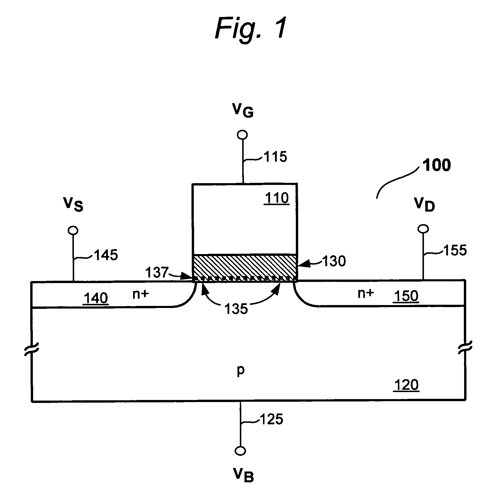
[0067]FIG. 1 shows a prior art NDR FET 100 of the type described in the King et al. applications noted earlier. This device is essentially a silicon based MISFET that includes an NDR characteristic as well. Thus, the features of device 100 are created with conventional MOS based FET processing, modified where appropriate as...


PUM


Abstract

A negative differential resistance (NDR) field-effect transistor element is disclosed, formed on a silicon-based substrate using conventional MOS manufacturing operations. Methods for improving a variety of NDR characteristics for an NDR element, such as peak-to-valley ratio (PVR), NDR onset voltage (VNDR) and related parameters are also disclosed.

Description

CROSS REFERENCE TO RELATED APPLICATIONS [0001] This application is a divisional of U.S. patent application Ser. No. 10 / 314,735 entitled “Method Of Forming A Negative Differential Resistance Device”, filed Dec. 9, 2002, and is related to the following applications, which are hereby incorporated by reference as if fully set forth herein: U.S. patent application Ser. No. 10 / 314,785, filed Dec. 9, 2002 entitled “Process for Controlling Performance Characteristics of a Negative Differential Resistance (NDR) Device”; and U.S. patent application Ser. No. 10 / 321,031, filed Dec. 17, 2002 entitled “Integrated Circuit Having Negative Differential Resistance (NDR) Devices With Varied Peak-to-Valley Ratios (PVRs)”.FIELD OF THE INVENTION [0002] This invention is directed to processes for making semiconductor devices, circuits, dies and systems, particularly those that utilize negative differential resistance (NDR) field-effect transistor (FET) elements. BACKGROUND OF THE INVENTION [0003] Silicon ...

Claims


Application Information

Patent Timeline
Patent Type & Authority Applications(United States)
IPC IPC(8): H01L21/265H01L21/8234H01L29/423H01L29/78
CPCH01L21/2652H01L29/78H01L29/42332H01L21/823462
Inventor KING, TSU-JAE
Owner SYNOPSYS INC
Learn More