Cascaded raman pump for raman amplification in optical systems
- Summary
- Abstract
- Description
- Claims
- Application Information
AI Technical Summary
Benefits of technology
Problems solved by technology
Method used
Image

Examples
example 1
[0053] The pump source 1 comprises a cw unpolarised cascaded Raman laser model PYL-1-1455 / 1486-P commercialised by IPG-Photonics Corporation (USA), which has two selectable cascaded lasers at different emission wavelengths of about 1455 nm and 1485; nm. The emission spectrum of the pump source of this example has the main emission line centred at about 4=1455 nm with full width at half maximum (FWHM) of 2-3 nm and is shown in FIG. 3 for a total pump power of 250 mW at the pump output (spectrum was measured after the coupler 6). Emission lines at lower wavelengths (i.e., lower-order Raman lines) λj=1, . . . , n-1 (n=is), with λn-1n, are visible in the spectrum. The difference of intensity between the lower-order Raman lines and the main emission peak at λn is about 25-35 dB. In other words, about 98% of the emitted power of the Raman laser of FIG. 3 is concentrated within 2-3 nm about λn.
[0054]FIG. 4 displays the ASE spectrum in arbitrary units, logarithmic (dB) scale, for a co-prop...
example 2
[0061]FIG. 9 shows the output power spectrum of a cw cascaded Raman laser commercialised by IPG-Photonics, PYL-1-1455 / 1486-P, from which the laser with main emission line at about 1485 nm was selected. The in-band optical power, i.e., the power centred at the main emission line, is about 98% of the total emitted power. Three lower-order Raman peaks are present in the spectrum of FIG. 8, which have a peak difference with the main emission line at 1485 nm of about 15-25 dB.
[0062] The ASE curve for a co-propagating pump having the output power spectrum of FIG. 9 and pump power of 150 mW is shown in FIG. 10. The transmission fibre for Raman amplification is that of Example 1. A strong anomalous peak is observed in the region of maximum gain, i.e., centred at about 1590 nm, due to parametric gain. This result acquires particular importance if we note that in the output spectrum of FIG. 9, the two first lower-order Raman lines, λn-1 and λn-2, are not clearly visible in the spectrum. Neve...
example 3
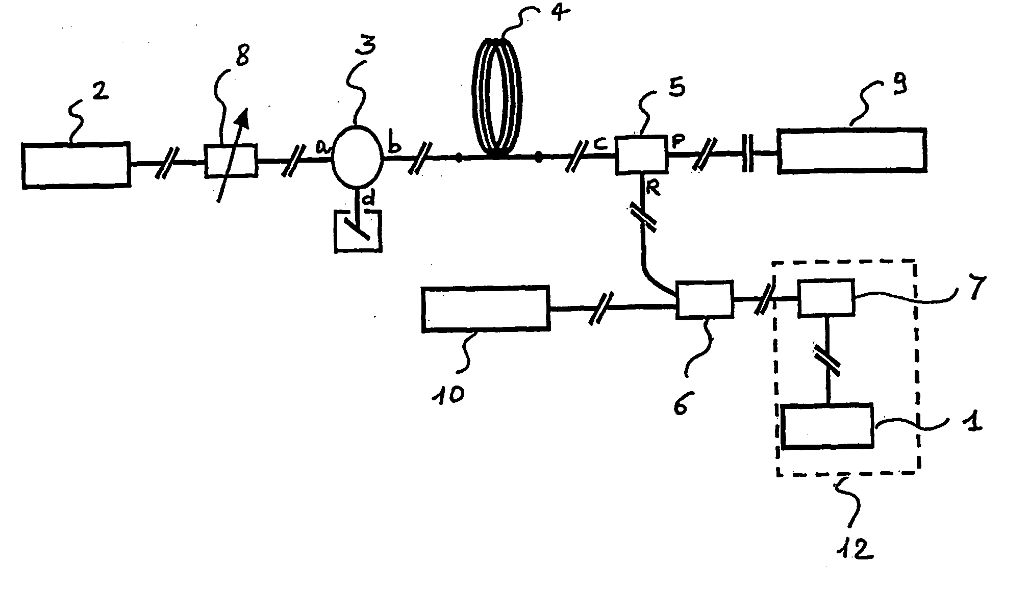
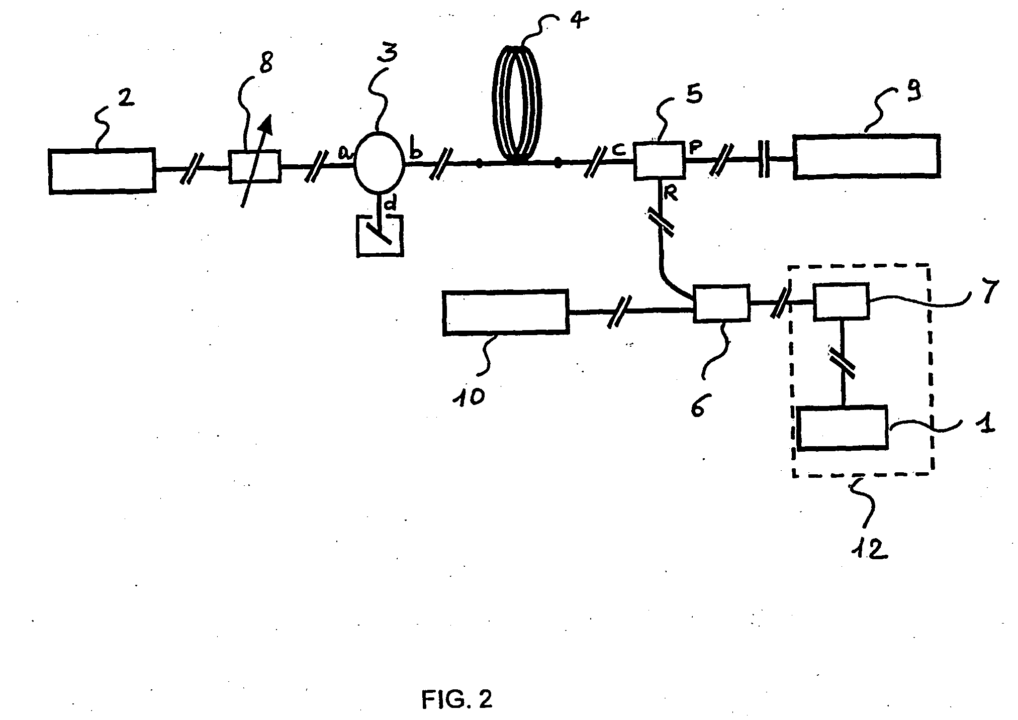
[0063]FIG. 11 schematically shows an optical transmission system according to the invention, which comprises a transmitting station 21, adapted to transmit optical signals over an optical fibre transmission line 14, and a receiving station 13, adapted to receive optical signals coming from the optical fibre line 14. The transmitting station 21 comprises a plurality of transmitters 21a, 21b, . . . 21m; m for example 32, 64 or 128. The receiving station 13 comprises a plurality of receivers 13a, 13b . . . , 13m. The transmission system may include transmitting and receiving stations and an optical fibre path for transmitting signals in a direction opposite to the direction of the optical fibre transmission line 14. Terminal and line apparatuses operating in the two directions often share installation sites and facilities.
[0064] The transmitters included in the transmitting station 21 provide an optical signal to be coupled into the optical fibre line 14. Typically, each transmitter m...
PUM
 Abstract
Description
Claims
Application Information
 - R&D
- Intellectual Property
- Life Sciences
- Materials
- Tech Scout
- Unparalleled Data Quality
- Higher Quality Content
- 60% Fewer Hallucinations
Browse by: Latest US Patents, China's latest patents, Technical Efficacy Thesaurus, Application Domain, Technology Topic, Popular Technical Reports.
© 2025 PatSnap. All rights reserved.Legal|Privacy policy|Modern Slavery Act Transparency Statement|Sitemap|About US| Contact US: help@patsnap.com