Portable vehicle exhaust flow sensor

Inactive Publication Date: 2005-11-24
FORD GLOBAL TECH LLC
View PDF13 Cites 26 Cited by
  • Summary
  • Abstract
  • Description
  • Claims
  • Application Information

AI Technical Summary

Benefits of technology

[0007] Embodiments of the present invention include a method for real-time determination of exhaust gas flow through an exhaust pipe of a vehicle. One method includes measuring a pressure difference upstream and downstream of a screen, measuring exhaust gas temperature, and determining the exhaust gas flow based on the pressure difference and the temperature. The exhaust gas flow may be determined based on a square root of the quotient of the pressure difference and the temperature, based on empirically determined exponents of the differential pressure and temperature, or based on a quadratic equation depending on the particular application. The screen preferably includes sufficient spacing to resist formation of condensation and minimize added back pressure while providing a measurable pressure drop to accurately determine exhaust gas flow from idle through full throttle operating conditions.
[0009] The present invention provides a number of advantages. For example, the present invention provides a portable exhaust flow sensor capable of accurately determining exhaust gas flows from idle through full throttle in real-time. The circular flow restricting element of the present invention includes sufficient spaces to resist formation of condensation and minimize added back pressure while providing an accurately measurable pressure drop for a wide range of flows. Systems and methods for determining exhaust gas flows according to the present invention provide accurate measurement of pulsating or reversing flows, such as those that may occur at idle in gasoline engines. In various embodiments, measurement sensitivity across the range of expected exhaust flows is improved by using two or more differential pressure transducers. Use of a thin screen or similar flow restriction element does not significantly increase the thermal capacity of the system and facilitates portability compared to conventional laminar flow measurement devices.

Problems solved by technology

Use of a thin screen or similar flow restriction element does not significantly increase the thermal capacity of the system and facilitates portability compared to conventional laminar flow measurement devices.

Method used


Image

  • Portable vehicle exhaust flow sensor
  • Portable vehicle exhaust flow sensor
  • Portable vehicle exhaust flow sensor

Examples


Embodiment Construction

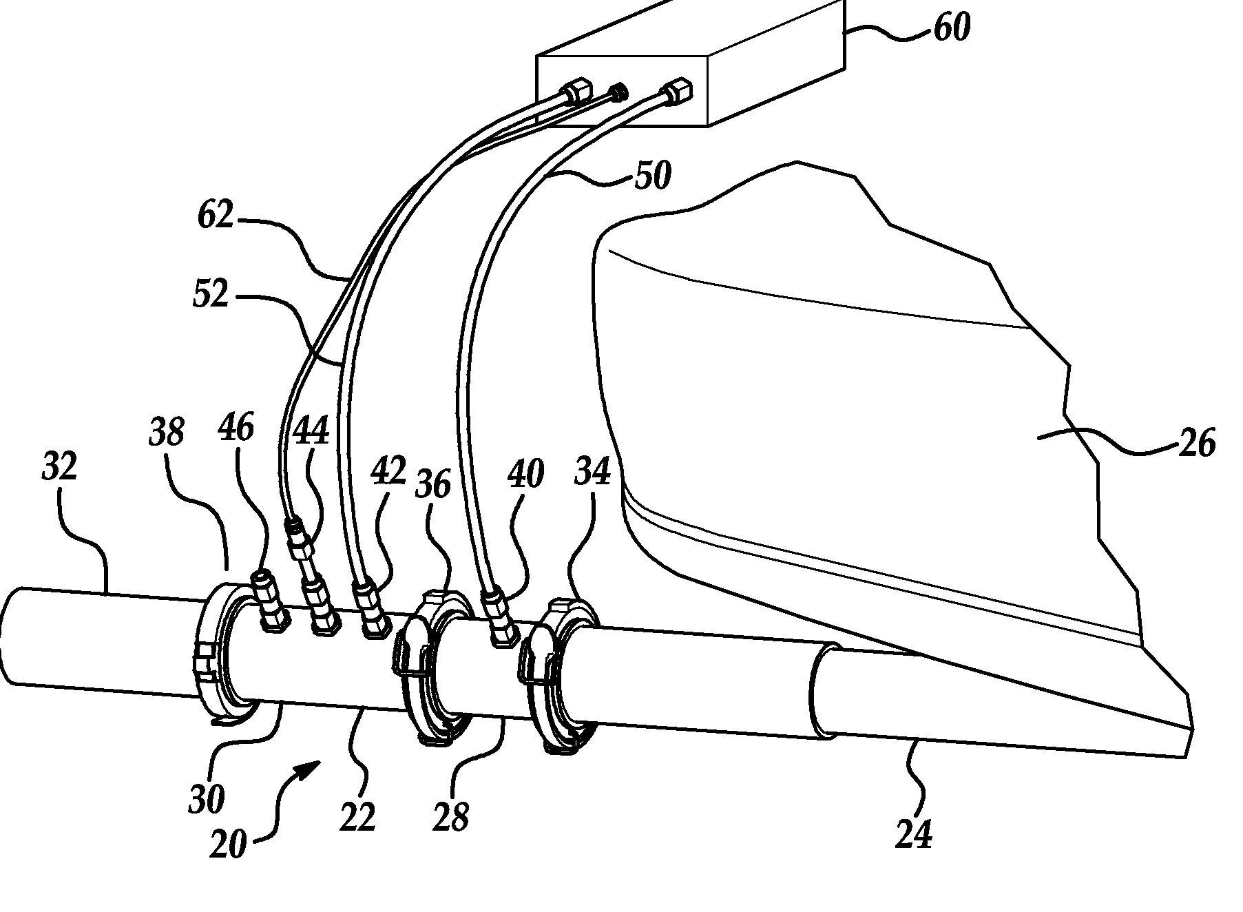
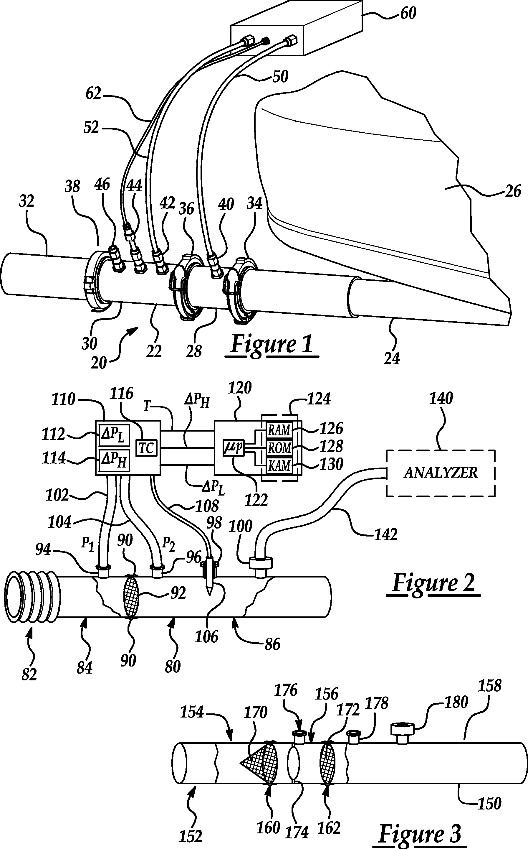
[0023]FIG. 1 is a perspective view of a representative installation for a vehicle exhaust gas flow sensor according to one embodiment of the present invention. As shown in FIG. 1, exhaust flow sensor 20 includes a tube 22 adapted for coupling to an exhaust (or tail) pipe 24 of a vehicle 26. As explained in greater detail below, exhaust flow sensor 20 may be used to measure exhaust gas flow and optionally sample exhaust gas for a variety of engine types and sizes including gasoline and diesel engines, for example. Similarly, exhaust flow sensor 20 may be adapted for installation on various types and sizes of engine exhaust pipes for real-time exhaust flow measurement during actual operation of the engine, including engines installed in automotive vehicles, marine vehicles, construction vehicles and equipment, etc.

[0024] In the embodiment illustrated in FIG. 1, tube 22 of exhaust flow sensor 20 includes a first (upstream) section or portion 28, a second (downstream) section or portio...


PUM


Abstract

A portable exhaust gas flow sensor includes a tube for coupling to an exhaust pipe of a vehicle. The tube includes a circular flow restricting element to induce a pressure drop based on the exhaust gas flow with an upstream port and a downstream port relative to the flow restricting element connected to a differential pressure transducer. A thermocouple extends through a temperature port to measure exhaust gas temperature flowing through the tube. A processor in communication with the thermocouple and the differential pressure transducer determines the exhaust gas flow based on the differential pressure and the temperature. The circular flow restricting element includes sufficient spaces to resist formation of condensation and minimize added back pressure while providing an accurately measurable pressure drop for flows ranging from idle to full throttle.

Description

BACKGROUND OF INVENTION [0001] 1. Field of the Invention [0002] The present invention relates to systems and methods for measuring exhaust gas flow rate of a vehicle. [0003]2. Background Art [0004] An accurate determination of the exhaust gas volumetric flow rate of a vehicle is useful for hardware, software, and calibration development in addition to testing compliance with various environmental regulations. While measurement of exhaust gas flows under actual operating conditions is preferable, it is often impractical with currently available devices. Instead, a vehicle or engine is operated under controlled conditions to simulate actual driving or operating conditions. Vehicle exhaust gases exhibit a wide range of flow rates and temperatures corresponding to varying operating modes and ambient conditions, which presents challenges to accurate flow rate measurement. Although a number of devices have been developed to measure exhaust gas flow rates, all have various disadvantages. [...

Claims


Application Information

Patent Timeline
IPC IPC(8): F01N11/00F02B33/44G01F1/36G01F1/40G01F1/50G01F1/88G01M99/00
CPCF01N2390/02G01F1/88G01F1/36G01F7/005
Inventor COLVIN, ALEXBUTLER, JAMESKORNISKI, THOMAS
Owner FORD GLOBAL TECH LLC
Why Eureka
Try Eureka