
Droplet ejecting apparatus, electro-optic device, electronic apparatus, and droplet ejecting method

Inactive Publication Date: 2005-11-17
SEIKO EPSON CORP
View PDF14 Cites 10 Cited by
  • Summary
  • Abstract
  • Description
  • Claims
  • Application Information

AI Technical Summary

Benefits of technology

[0010] An advantage of the invention is to provide a droplet ejecting apparatus, an electro-optic device, an electronic apparatus, and a droplet ejecting method which are capable of decreasing the number of steps for drawing in three colors R, G, and B on a substrate, thereby decreasing the manufacturing cost.
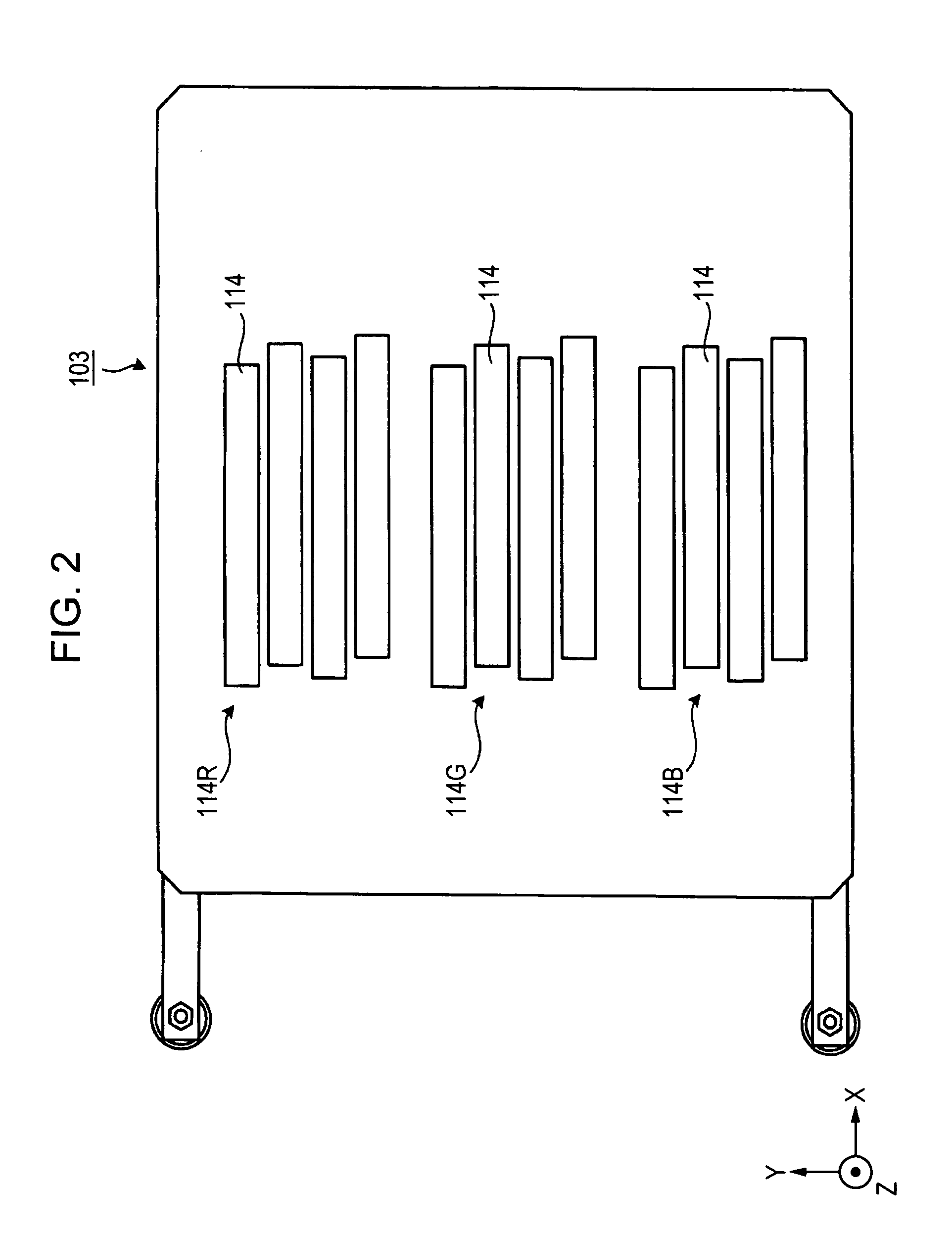
[0011] In order to solve the problem and achieve the advantage, a droplet ejecting apparatus according to an aspect of the present invention comprises a stage for holding a substrate, head groups for R, G, and B colors for ejecting droplets of R, G, and B colors, respectively, each of the head groups comprising at least one head, and a carriage for holding the head groups for the R, G, and B colors so that the head groups overlap each other in a first direction. In the apparatus, during movement of the carriage relative to the stage in the first direction, droplets of the R, G, and B colors are ejected to R, G, and B colored portions on the substrate from the head groups for the R, G, and B colors, respectively.
[0012] During movement of the carriage relative to the stage in the first direction, the droplets of the R, G, and B colors are ejected to R, G, and B colored portions from the head groups for the R, G, and B colors, respectively. Thus, during one relative movement in the first direction, drawing can be performed in all of the R, G, and B colored portions within the plotting width of the head group. Therefore, drawing in three colors R, G, and B can be simultaneously performed on the substrate by one step. As a result, the droplet ejecting apparatus is capable of decreasing the number of the steps in drawing in the three colors R, G, and B on the substrate and decreasing the manufacturing cost.
[0013] In the present invention, each of the R, G, and B colored portions preferably has a substantially rectangular planar shape determined by long and short sides, and the stage preferably holds the substrate so that the long side is parallel to a second direction perpendicular to the first direction, and the short side is parallel to the first direction. As a result, stripe-shaped R, G, and B colored portions can be drawn.
[0014] The nozzle arrays of the heads in the head groups for the R, G, and B colors are preferably arranged in parallel to the second direction perpendicular to the first direction. As a result, high-definition drawing can be performed within a wide drawing width.
[0015] The nozzle arrays of the heads in each of the head groups for the R, G, and B colors are preferably arranged in a direction oblique to the second direction perpendicular to the first direction. As a result, high-definition drawing can be performed within a wide drawing width.

Problems solved by technology

However, in the spin coating method, the supplied liquid material is mostly scattered, and thus a large amount of the liquid material is required to increase waste and manufacturing cost.
However, the above-mentioned related art has the problem that the same step is must be repeated three times for drawing in the three colors R, G, and B on a substrate, thereby increasing the number of the steps and manufacturing cost.

Method used


Image

  • Droplet ejecting apparatus, electro-optic device, electronic apparatus, and droplet ejecting method
  • Droplet ejecting apparatus, electro-optic device, electronic apparatus, and droplet ejecting method
  • Droplet ejecting apparatus, electro-optic device, electronic apparatus, and droplet ejecting method

Examples


embodiments

[0060] A droplet ejecting apparatus, an electro-optic device, and an electronic apparatus according to preferred embodiments of the present invention will be described in detail below.

(Droplet Ejecting Apparatus)

[0061] A droplet ejecting apparatus according an embodiment of the present invention will be described in detail below in the order of “Whole configuration of droplet ejecting apparatus”, “Carriage”, “Head”, “Head group”, “Control unit”, “Ejection method”, “Modified example of ejection method”, and “Modified example of head arrangement”.

(Whole Configuration of Droplet Ejecting Apparatus)

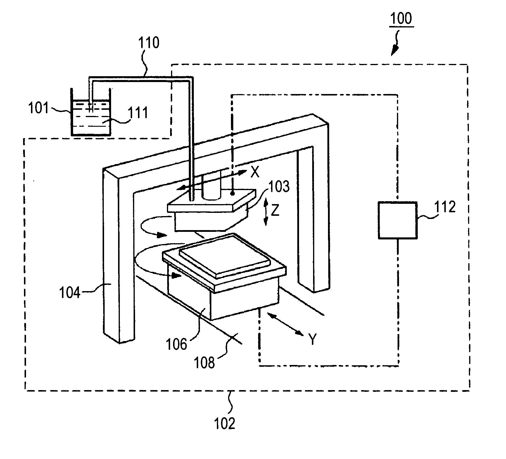
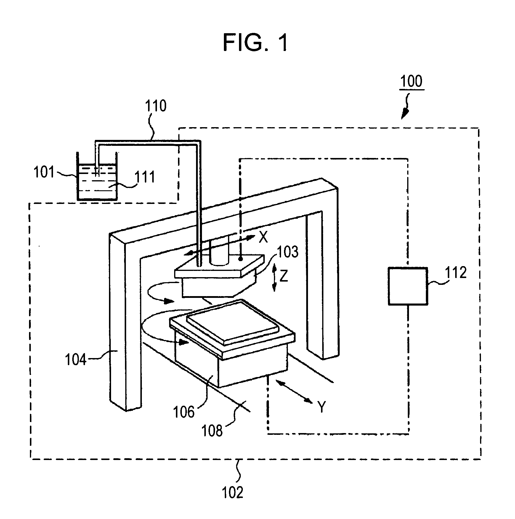
[0062] As shown in FIG. 1, a droplet ejecting apparatus 100 comprises a tank 101 holding a liquid material 111, a tube 110, and an ejection scanning unit 102 to which the liquid material 111 is supplied from the tank 101 through the tube 110. The ejection scanning unit 102 comprises a carriage 103 holding a plurality of heads 114 (FIG. 2), a first position control device 104 for control...


PUM


Abstract

A droplet ejecting apparatus includes a stage which holds a substrate; R (red), G (green), and B (blue) head groups for ejecting droplets of the R, G, and B colors, respectively, each of the head groups including at least one head; and a carriage which holds the R, G, and B head groups. In the apparatus, droplets of the R, G, and B colors are ejected to R, G, and B colored portions on the substrate from the R, G, and B head groups, respectively, during movement of the carriage relative to the stage in a first direction.

Description

BACKGROUND OF THE INVENTION [0001] 1. Technical Field [0002] The present invention relates to a droplet ejecting apparatus, an electro-optic device, an electronic apparatus, and a droplet ejecting method. Specifically, the present invention relates to a droplet ejecting apparatus suitable for applying a liquid material to regions periodically arranged in a color filter substrate, a color matrix display, or the like, an electro-optic device, an electronic apparatus, and a droplet ejecting method. [0003] 2. Related Art [0004] For example, a spin coating method, which is a thin-film forming method, is generally used for forming a thin film. In the spin coating method, a liquid material is applied in the form of droplets to a substrate, and then the substrate is rotated to spread the liquid material over the entire surface of the substrate by centrifugal force, thereby forming a thin film. The thickness of the thin film is controlled by controlling the rotational speed, the rotation hol...

Claims


Application Information

Patent Timeline
IPC IPC(8): B41J2/01B41J2/205G02B5/20H01L51/40
CPCH01L51/0004G02B5/201H10K71/13G02F1/1335
Inventor MATSUMOTO, RYOICHIOKUSA, TAKASHI
Owner SEIKO EPSON CORP
Learn More