
Antireflection film for plasma display

Inactive Publication Date: 2006-12-21
DAI NIPPON PRINTING CO LTD
View PDF1 Cites 30 Cited by
  • Summary
  • Abstract
  • Description
  • Claims
  • Application Information

AI Technical Summary

Benefits of technology

[0014] The present invention was accomplished in order to solve the aforementioned problems in the prior art. An object of the present invention is to make it possible to shield unwanted light emitted from a PDP and also to impart, to the PDP, the property of preventing reflection of light by laminating one film to the PDP. Namely, an object of the present invention is to provide, in a minimum number of lamination steps, a durable anti-reflection film for a plasma display having the property of shielding near infrared rays and / or unwanted light with specific wavelengths originating from the emission spectrum of an insert gas, capable of imparting, to a plasma display, the property of preventing reflection of extraneous light, thereby making the plasma display satisfactorily reproduce natural color, provide improved image visibility, cause no malfunction of remote controllers that is usually caused by near infrared rays, and stably maintain the image visibility for a prolonged period of time.
[0027] The present invention provides an anti-reflection film for plasma display that has moderate transparency and luminance and the property of preventing reflection of light, can shield near infrared rays with wavelengths of 800 to 1,100 nm, and can optimize the color quality to improve image quality by correcting the inherent emission spectrum of an insert gas characteristic of a PDP and adjusting the color tone of a displayed image to a favorite one.
[0028] The present invention provides an anti-reflection film for plasma display that can form, together with other layers such as an electromagnetic wave shielding film and a substrate, a front panel for a plasma display with ease.
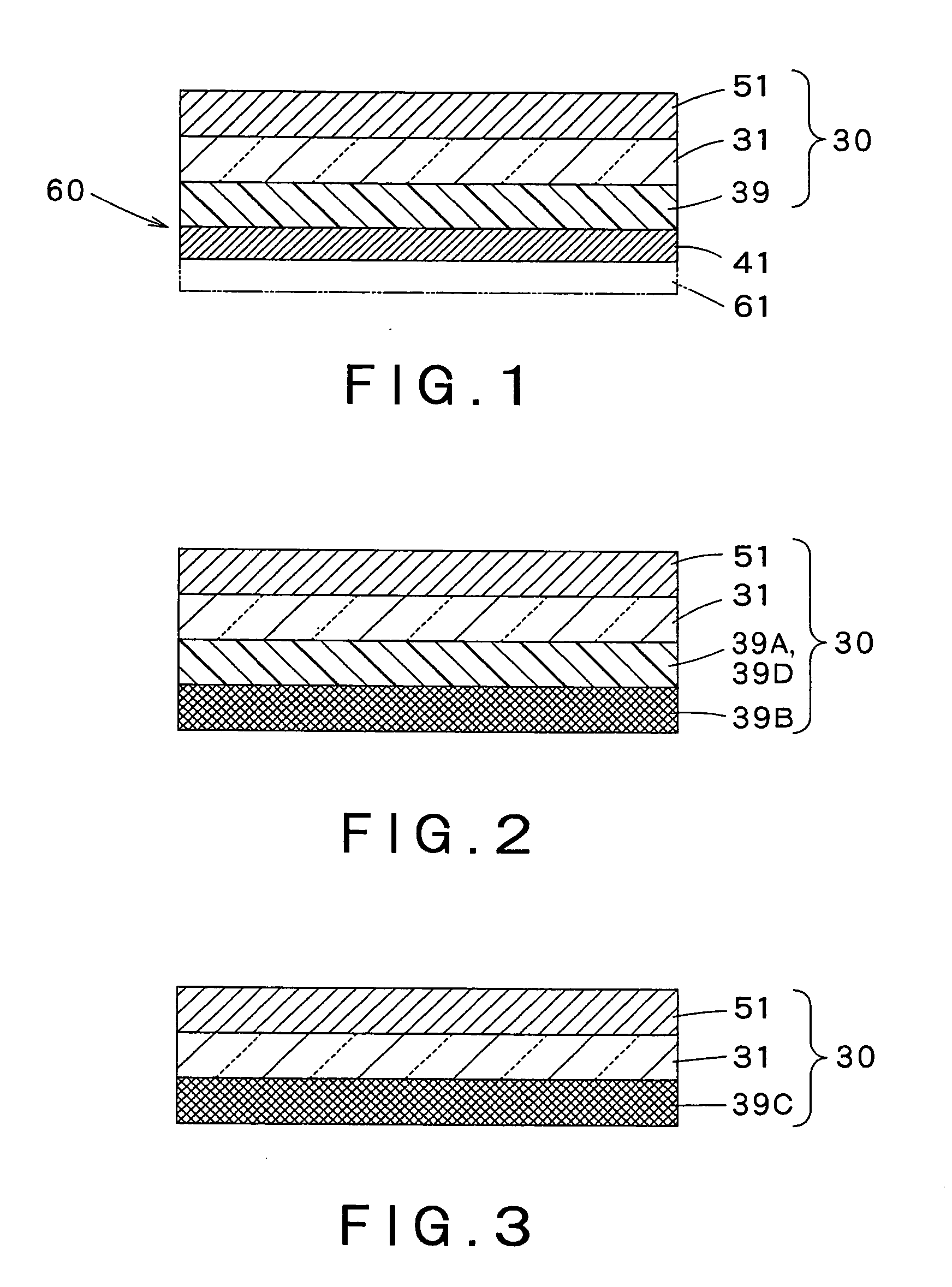
[0029] According to the present invention, since a coloring agent for absorbing near infrared rays and a coloring agent for absorbing light with specific wavelengths originating from the emission spectrum of an insert gas are incorporated in different layers, it is easy to control only the coloring agent for color tone correction that requires the adjustment of transmittance, and there is provided an anti-reflection film for plasma display that can stably maintain the visibility of a displayed image for a long period of time.
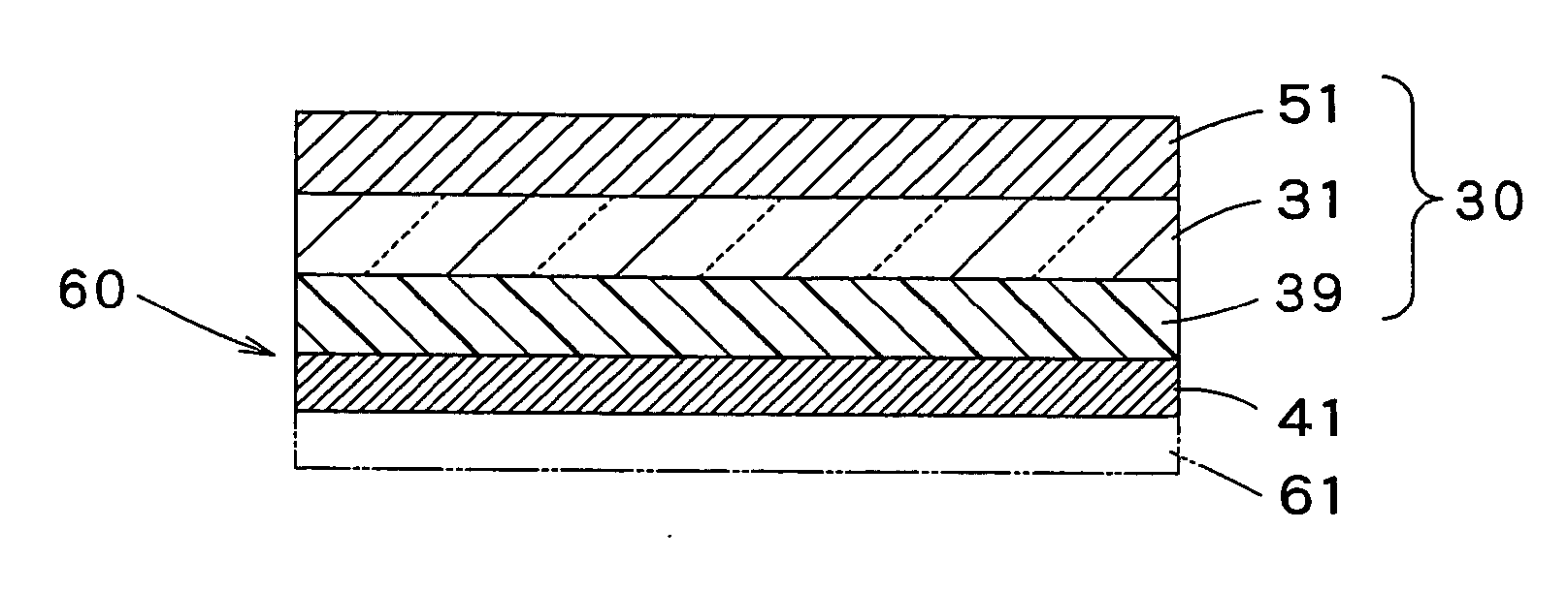
[0031] According to the present invention, since an anti-reflection layer, a near infrared rays absorbing layer, and a specific-wavelength-light absorbing layer are integrally formed in advance, the number of layers to be laminated is small, and, moreover, a front panel for a plasma display can be produced in a decreased number of steps; there is thus provided an inexpensive anti-reflection film for a plasma display.
[0032] According to the present invention, since an ultraviolet light absorber is incorporated in at least one layer selected from the transparent substrate film and the layers provided on the transparent substrate film on the side opposite to the unwanted light shielding layer (external side), there is provided a light-fast anti-reflection film for plasma display in which the coloring agent contained in the unwanted light shielding layer does not undergo deterioration by ultraviolet light contained in extraneous light such as sunlight and neither loses its ability to absorb near infrared rays nor undergoes change in color such as yellowing.

Problems solved by technology

Since dyes are incorporated in the substrates of the optical display filters disclosed in these publications, these filters are disadvantageous in that their production processes demand the step of incorporating dyes and also facilities and materials that are used in this step, which leads to increase in cost.

Method used


Image

  • Antireflection film for plasma display
  • Antireflection film for plasma display

Examples


example 1

[0090] An anti-reflection film TAC-AR1 (trademark, manufactured by Dai Nippon Printing Co., Ltd., Japan) produced by successively laminating a hard coat layer, a low refractive index layer, and an anti-staining layer to one surface of an 80-μm thick triacetyl cellulose (TAC) film as the substrate film 31 was prepared. The following unwanted-light-shielding-layer-forming composition was applied to the surface of the TAC film on the side opposite to the hard coat layer and was dried to form an unwanted light shielding layer.

[0091] The unwanted-light-shielding-layer-forming composition was prepared in the following manner: the following coloring agents were dispersed or dissolved in methyl ethyl ketone, and this dispersion or solution was mixed with a transparent acrylic resin; the viscosity of the mixture as measured by a zane cup No. 3 (manufactured by Rigo Kabushiki Kaisha, Japan) was then adjusted to 20 seconds. The coloring agents used were as follows: a diimmonium colorant CIR 1...

example 2

[0093] An anti-reflection film for a plasma display was obtained in the same manner as in Example 1, except that, of the coloring agents, only the near infrared rays absorbing agents (NIR absorbing agents) and the coloring agent for color tone correction (Ne light absorbing agent) were incorporated in the unwanted-light-shielding-layer-forming composition.

example 3

[0094] An anti-reflection film for a plasma display was obtained in the same manner as in Example 1, except that, of the coloring agents, only the near infrared rays absorbing agents (NIR absorbing agents) were incorporated in the unwanted-light-shielding-layer-forming composition.


PUM

PropertyMeasurementUnit
Transparencyaaaaaaaaaa
Sensitivityaaaaaaaaaa
Wavelengthaaaaaaaaaa

Abstract

An anti-reflection layer 51 is provided on one surface of a transparent substrate film 31. A specific-wavelength-light shielding layer 39 containing a coloring agent for color tone correction capable of absorbing light with specific wavelengths originating from the emission spectrum of an insert gas of a PDP, and / or a near infrared rays absorbing agent, is provided on the other surface of the transparent substrate film 31. Further, a pressure-sensitive adhesive layer 41 is optionally provided on the specific-wavelength-light shielding layer 39.

Description

FIELD OF THE INVENTION [0001] The present invention relates to an anti-reflection film for a plasma display, and, more particularly, to an anti-reflection film for a plasma display that is placed on the front of a plasma display element (also referred to as a PDP) so as to shield near infrared rays that are emitted from the element and also to prevent reflection of extraneous light from the screen of the element, thereby making an image displayed on a display (also referred to as an image display) highly visible. BACKGROUND ART [0002] In this Specification, “ratio”, “part”, “%”, and the like that indicate proportions are on a weight basis unless otherwise specified, and the symbol “ / ” denotes that layers enumerated together with it are integrally laminated. Further, “PDP” designates a “plasma display element”; “NIR”, near infrared rays”; “EMI”, “electromagnetic waves”; and “PET”, “polyethylene terephthalate”. Furthermore, the word “anti-reflection (or preventing reflection of (extra...

Claims


Application Information

Patent Timeline
IPC IPC(8): B32B27/20G02B1/10G02B1/11G02B5/20
CPCG02B1/11Y10T428/31504G02B5/20G02B1/10
Inventor NAITO, NOBUOARAKAWA, FUMIHIROMASAKI, TADAHIRO
Owner DAI NIPPON PRINTING CO LTD
Learn More