
Communication control circuit

Inactive Publication Date: 2005-07-05
NEC ELECTRONICS CORP
View PDF6 Cites 8 Cited by
  • Summary
  • Abstract
  • Description
  • Claims
  • Application Information

AI Technical Summary

Benefits of technology

[0127]An operation test and also tests other than an operation test can therefore be conducted on the same LSI, whereby the number of steps can be reduced compared to loopback tests that were heretofore performed using special devices, and the number of steps of overall tests can be decreased.

Problems solved by technology

This method of the prior art is therefore problematic due to its complexity.
The use of this cable, however, causes the problem that tests on each of the LSI are more difficult, and there has consequently been demand for operation tests that are performed on each LSI.
However, since wiring and switches are provided between the ports, this test circuit has the problem that the parasitic capacitance of the wiring and switches obstructs high-speed operation during normal operation.
Although it is possible to use an LSI tester capable of high-speed operation to perform a test on an LSI at a high speed equivalent to normal speed, such LSI testers that operate at high speed are expensive.

Method used


Image

  • Communication control circuit
  • Communication control circuit
  • Communication control circuit

Examples


Embodiment Construction

[0148]Turning now to the accompanying figures, the first embodiment of the present invention is next explained.

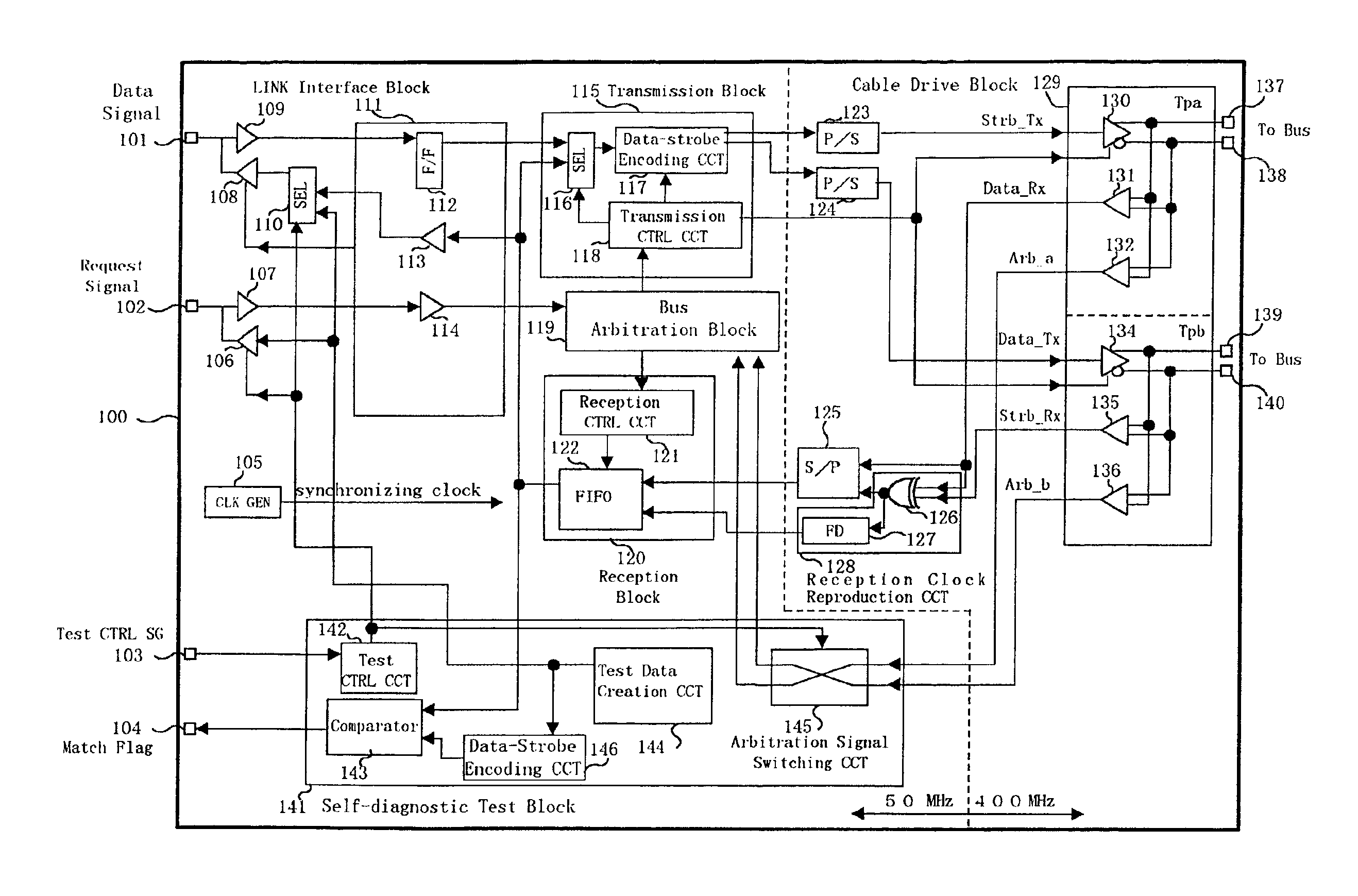
[0149]FIG. 14 is a block diagram of a communication control circuit according to the first embodiment of the present invention. The communication control circuit of this embodiment incorporates a self-diagnostic test circuit in an LSI of the PHY circuit of FIG. 7. Components in FIG. 14 having the same reference numbers as components in FIG. 7 have the same function as the components in FIG. 7.

[0150]Referring now to FIG. 14, communication control circuit 100 of the first embodiment of the present invention includes as its principal constituent elements: LINK interface block 111, cable drive block 129, transmission block 115, reception block 120, bus arbitration block 119, and self-diagnostic test block 141.

[0151]Communication control circuit 100 is further provided with P / S circuits 123 and 124 and S / P circuit 125 at the interface with serial data processor (cable drive bloc...


PUM


Abstract

The invention provides a communication control device that includes a self-diagnostic test circuit capable of executing an operation test. The communication control circuit includes a PHY circuit on an LSI with little trouble, and at a operating speed that is equivalent to actual operation. The self-diagnostic test circuit includes: test data creation circuit for creating test data; expected value data creation circuit for creating expected values of the test data after processing; an arbitration signal switching circuit that switches arbitration signals such that test data supplied from the output driver can be received by a receiver of the same twisted-pair drive block as the output driver; and a comparison circuit that compares test data supplied from an output driver and received by a receiver of the same twisted-pair drive block as the output driver with the expected value data and creates match flags.

Description

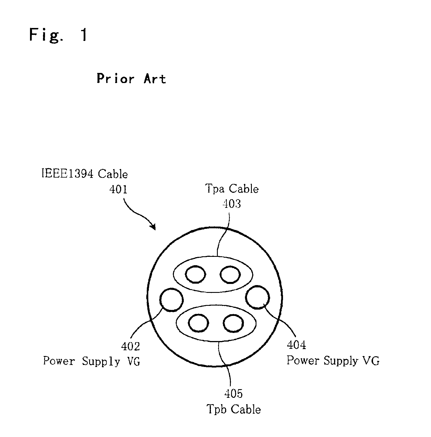
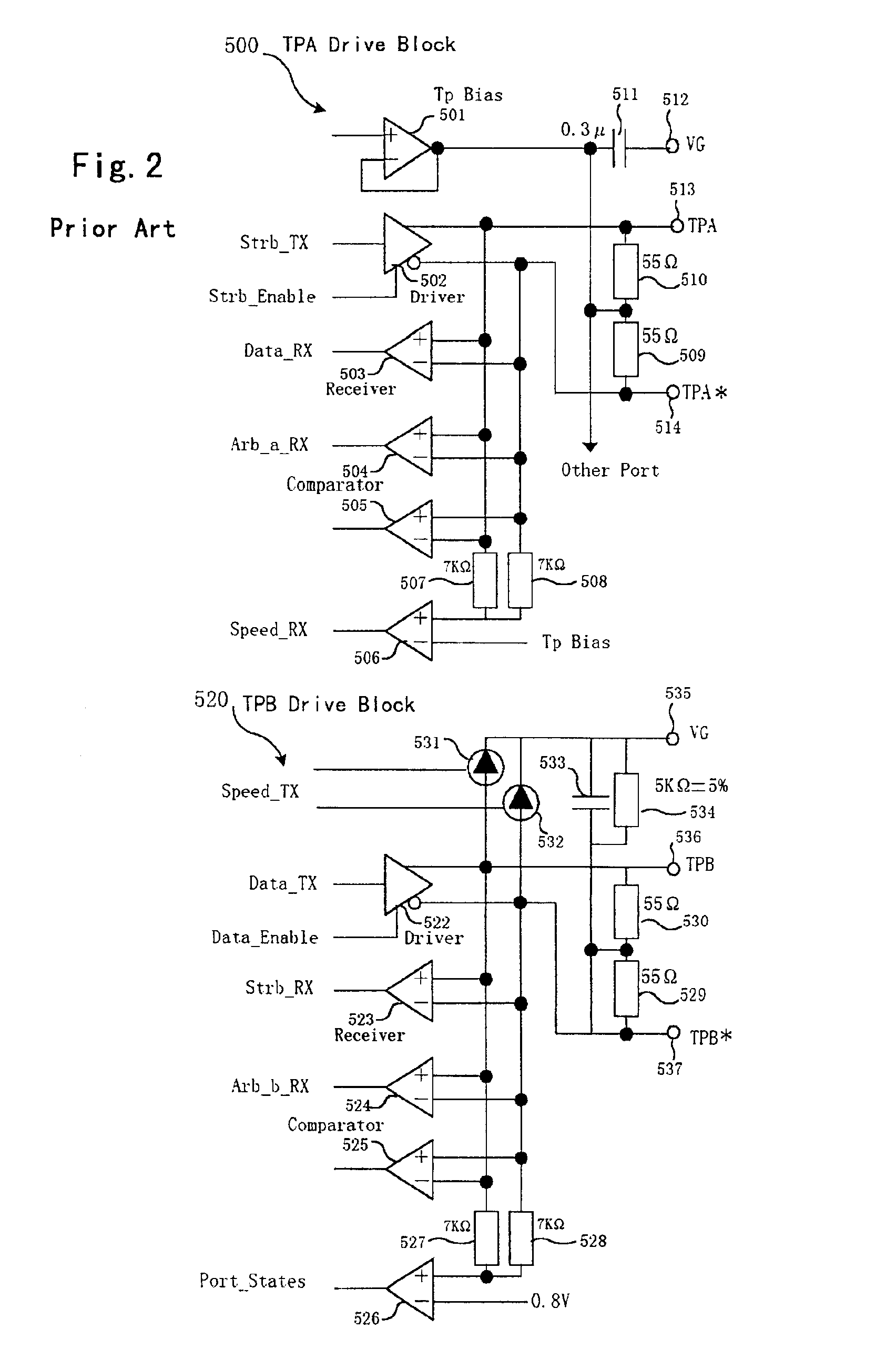
BACKGROUND OF THE INVENTION[0001]1. Field of the Invention[0002]The present invention relates to a communication control circuit, and particularly to a communication control circuit including a physical layer driver circuit (PHY circuit) in compliance with the IEEE (Institute of Electrical and Electronic Engineers) Standard 1394.[0003]2. Description of the Related Art[0004]Recent years have seen the development of a variety of bus standards for personal computer peripheral devices as computer interfaces. These bus standards for personal computer peripheral device include USB (Universal Serial Bus) standards and high-performance serial bus standards pursuant to IEEE Standard 1394. IEEE Standard 1394 is a standard for a high-speed serial bus that was developed principally by Apple Computer, Inc. This standard specifies physical and electrical standards for cables and connectors for interconnecting a wide range of devices including home-appliances, and defines international standards r...

Claims


Application Information

Patent Timeline
IPC IPC(8): H04L1/24H04B3/46G06F13/00G06F11/22H04L12/28H04L12/40H04L69/40
CPCH04B3/46H04L1/243
Inventor MATSUO, SYUJITANAKA, KIYOSHI
Owner NEC ELECTRONICS CORP
Learn More