
Temperature probe adapter

a technology of temperature probe and adapter, which is applied in the field of electronic thermometers, can solve the problems of spreading contamination to other probes, affecting the accuracy of the temperature probe, so as to improve accuracy, improve performance and accuracy, and reduce linearity errors

Inactive Publication Date: 2005-11-10
YERLIKAYA Y DENNIS +1
View PDF9 Cites 53 Cited by
  • Summary
  • Abstract
  • Description
  • Claims
  • Application Information

AI Technical Summary

Benefits of technology

[0022] The present invention reduces patient exposure to all sources of cross-contamination, aids in infection control, and provides a clean, uncontaminated, readily accessible source of probe covers. Embodiments of the present invention feature a probe assembly for an electronic thermometer, which does not require expensive calibration procedures during manufacturing and allows the use of inexpensive thermisters. A memory component such as an EEPROM stores calibration information and identifying information in the probe assembly.
[0025] The invention of the present disclosure is particularly useful in electronic thermometers having interchangeable probe assemblies. Features of the invention include instant automatic identification of a temperature probe in a removable module. Effective interchangeability of different types of removable module—based temperature probes or different probes of the same type is featured without requiring labor intensive hardware modification.
[0026] The invention further features improved performance and accuracy over prior art electronic thermometers. Embodiments of the invention feature more than one temperature sensor in a temperature probe for improved accuracy.
[0027] The invention also features storage of all calibration parameters of the temperature sensors including calibration data for at least two different reference temperatures. This feature of the invention reduces linearity errors and improves a regression process used in the temperature calculation algorithm.
[0028] The invention further features the use of a low cost, low thermal mass thermistor chip having a wide tolerance. This feature of the invention improves the thermal time constant and the overall response time of the thermometer as compared to conventional electronic thermometers which require tighter tolerance bulky glass bead type thermistors.
[0029] Further features of the invention include the reduction or elimination of calibration costs during manufacturing of temperature probe. Manufacturing costs are further reduced by mounting the memory component on the same small circuit board that acts as an interface between the probe cable conductors and their connector pins. Embodiments of the invention feature encapsulation of the memory components in a strain relief portion of the probe cable. Such encapsulation provides protection against fluid incursion into the electronic components and probe cable.

Problems solved by technology

In typical use, prior art electronic thermometers are susceptible to at least three major sources of contamination.
Even though disposable plastic probe covers are used for each measurement, cross-contamination may still result from use of the same probe.
The second source of contamination involves the probe storage chamber.
This recess, once contaminated, may spread contamination to other probes as they may be interchangeably stored in the same recess.
Over time, the storage chamber may also collect debris and contamination from the storage of multiple probes.
The third source of contamination relates to the disposable probe covers.
The probe, then, once contaminated, may spread contamination to other unused probe covers.
Such practice, however, requires two thermometer units to be available at each location if the probes are not interchangeable.
Maintaining two units at each location has been considered an inefficient and costly measure.
Such a practice also makes the practitioner susceptible to using the most convenient, yet inappropriate, unit.
A significant limitation of each of these approaches is that, even though the probe is permanently attached to an isolation chamber, both the oral and rectal probe units will be repeatedly and interchangeably inserted into the same box or boxes of probe covers, still exposing the probe to possible contamination.
Both oral and rectal probe units share access to the same source of probe covers, providing a source of cross-contamination.
Each of these prior art approaches fail to address the exposure to contamination as each temperature sensitive probe, oral or rectal, is repeatedly inserted into the same box or boxes of probe covers.
The calibration procedure is costly because it is labor intensive.
These expensive thermistors also have a high thermal mass which increases the response time of the thermometer.
Single point calibration causes relatively high linearity errors in temperature calculations resulting in decreased accuracy.
The high costs associated with probe / sensor calibration and use of tight tolerance thermistors has made the use of multiple thermistors impractical in most probe applications.
Component costs have thereby rendered impractical the use of these more accurate temperature calculation algorithms.
Although color coding and other identifying features has made probe units identifiable to users, interchangeable probe units of different types are not typically identifiable by the electronic hardware.
This limits the ability of the temperature calculation components to adapt to variations between the probe unit types.

Method used


Image

  • Temperature probe adapter
  • Temperature probe adapter
  • Temperature probe adapter

Examples


Embodiment Construction

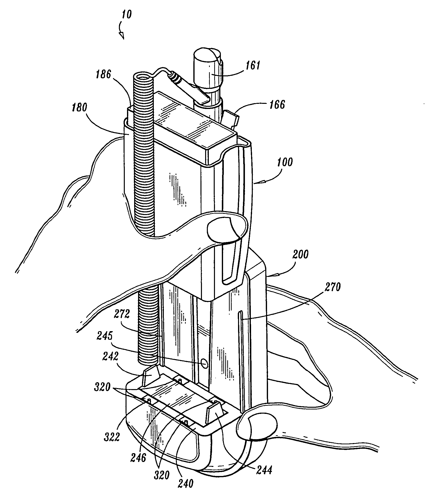
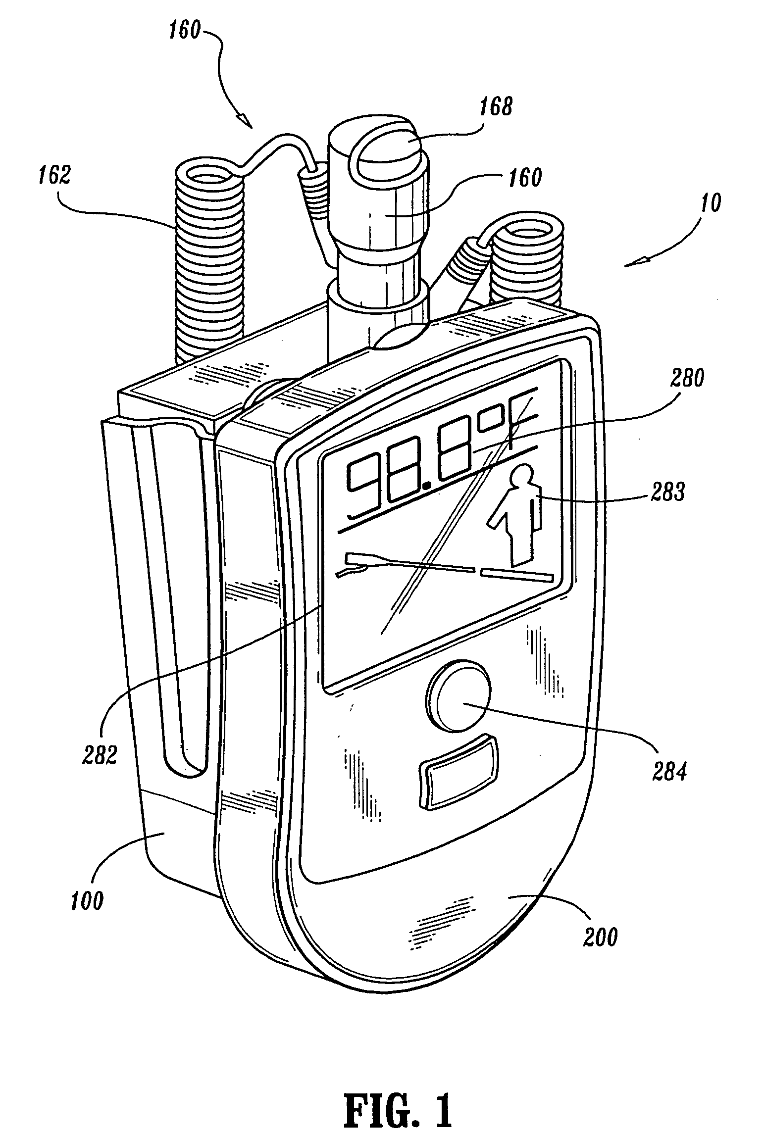
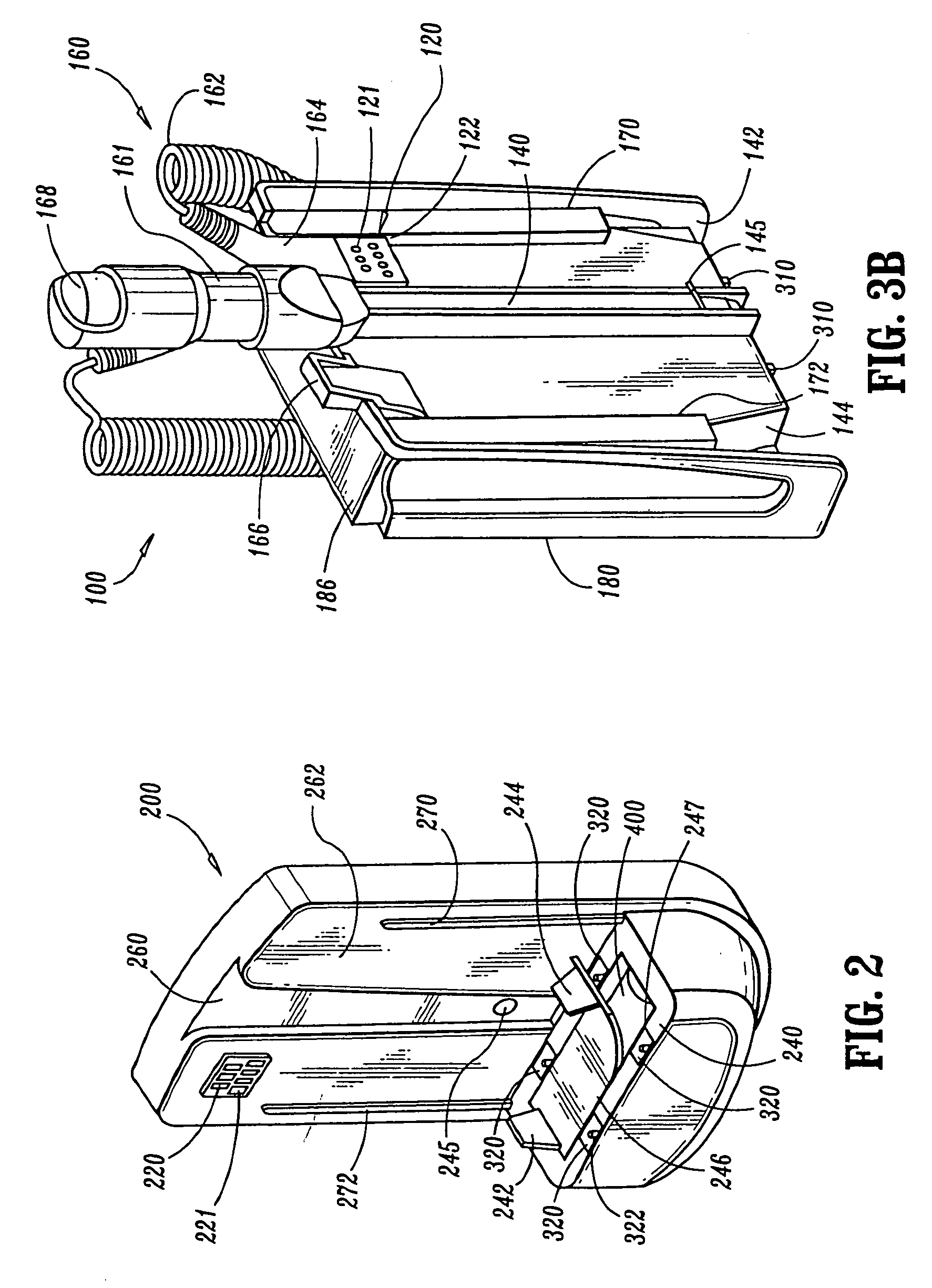
[0045] Reference is now made to the embodiments illustrated in FIGS. 1-9C wherein like numerals are used to designate like parts throughout. In cases where parts have similar form and function, similar numerals may be used for ease in interpretative cross referencing.

[0046] Referring to FIG. 1, a thermometer according to the present invention is shown. The thermometer includes a temperature calculating unit and a removable module that is mated and secured to the temperature calculating unit. When the removable module is secured to the temperature calculating unit, a connector assembly component and a mating header assembly component are properly aligned and together form an electrical connection. This electrical connection allows a signal detected by a temperature probe to be transmitted from the removable module to the temperature calculating unit. Once received, the temperature calculating unit converts the signal to a temperature reading. The temperature reading is observed thro...


PUM


Abstract

An electronic thermometer that reduces patient exposure to all sources of cross-contamination, aids in infection control, and provides a clean, uncontaminated, readily accessible source of probe covers. A probe assembly for an electronic thermometer, which does not require expensive calibration procedures during manufacturing and allows the use of inexpensive thermisters. A memory component such as an EEPROM integrated circuit stores calibration information and identifying information in each particular probe assembly which improves performance and reduces manufacturing costs.

Description

CROSS REFERENCE TO RELATED APPLICATIONS [0001] The present application is a continuation of patent application Ser. No. 09 / 942,334, filed on Aug. 28, 2001, which claims the benefit of U.S. Provisional Application No. 60 / 301,395, which was filed on Jun. 27, 2001, which are hereby incorporated by reference.FIELD OF THE INVENTION [0002] This invention relates to electronic thermometers, in particular, to electronic thermometers having interchangeable or removable temperature probes. BACKGROUND OF THE INVENTION [0003] Electronic thermometers have been widely used for quick and accurate measurements of body temperature. A temperature sensing probe is inserted orally, rectally, or in an axillary (under the arm) position to measure a patient's temperature. The temperature sensitive probe is connected to thermal circuitry in a temperature calculating unit by an electrical cable. The temperature sensitive probe generates a signal. This signal passes through the electric cable to the temperat...

Claims


Application Information

Patent Timeline
IPC IPC(8): G01K7/00G01K1/02G01K13/00G01K15/00
CPCG01K15/00G01K13/002G01K13/20
Inventor YERLIKAYA, Y. DENNISBABKES, MITCHELL H.
Owner YERLIKAYA Y DENNIS
Learn More