
Music instrument system and methods

a technology of instruments and instruments, applied in the field of instruments, can solve the problems of system system changes that are not likely to produce pleasing or entertaining sounds, etc., and achieve the effect of easy production of pleasing musi

Inactive Publication Date: 2005-11-03
TOPDOWN LICENSING LLC
View PDF43 Cites 30 Cited by
  • Summary
  • Abstract
  • Description
  • Claims
  • Application Information

AI Technical Summary

Benefits of technology

Enables novice performers to produce consistently pleasing and harmonious music using fine, precise movements, adaptable to various settings, including small areas and portable use, while allowing for increasing control over sound generation as the performer becomes more skilled.

Problems solved by technology

Some of these attempts include setting up various electromagnetic beams / patterns in the area whereby movement of a person / people interferes with these beams / patterns and causes sound generation.
With such systems, even slight movement variations can cause undesirable changes in pitch, tone, volume, or the like.
While such systems permit a highly-trained person to “play” the system and generate exactly certain sounds at each “performance” in a more-or-less “professional” manner, these systems are not likely to produce pleasing or entertaining sounds or results if a novice attempts to perform on them.
Additionally, such prior art systems generally comprise relatively large areas around which are placed the light beams used for playing music or producing sounds.
Such prior art systems are also relatively large and cage-like.
Furthermore, such systems generally require that the beam or sensor have interaction with either a substantial part of the user's body, or at least that the beam or sensor be interrupted by an arm or a full hand.
Thus, such systems also require relatively gross movements for their operation.
Such systems therefore are not adapted for fine, precise, and economical user movements.
Moreover, such systems are generally fairly large and require permanent or semi-permanent installations.

Method used


Image

  • Music instrument system and methods
  • Music instrument system and methods
  • Music instrument system and methods

Examples


Embodiment Construction

[0040] General MIDI Description

[0041] MIDI is an acronym for Musical Instrument Digital Interface. Additional information about MIDI, including technical specifications related thereto, can be obtained on the World Wide Web from the MIDI Manufacturer's Association. It is noted that the difference between MIDI and digital audio is that MIDI is merely performance data which by itself does not produce an audible output of sound. Instead, production of audible sound from MIDI data requires a MIDI instrument. Generally MIDI instruments tend to be of the MIDI synthesizer keyboard or module type, and are considered to be hardware-based synthesizers. However, in addition to the hardware synthesizers, software synthesizers are also available. Such software synthesizers are possible due to the computational power available to modern personal computers. The combination of a personal computer and appropriate synthesizer software can result in a fully capable and fully functional MIDI synthesiz...


PUM


Abstract

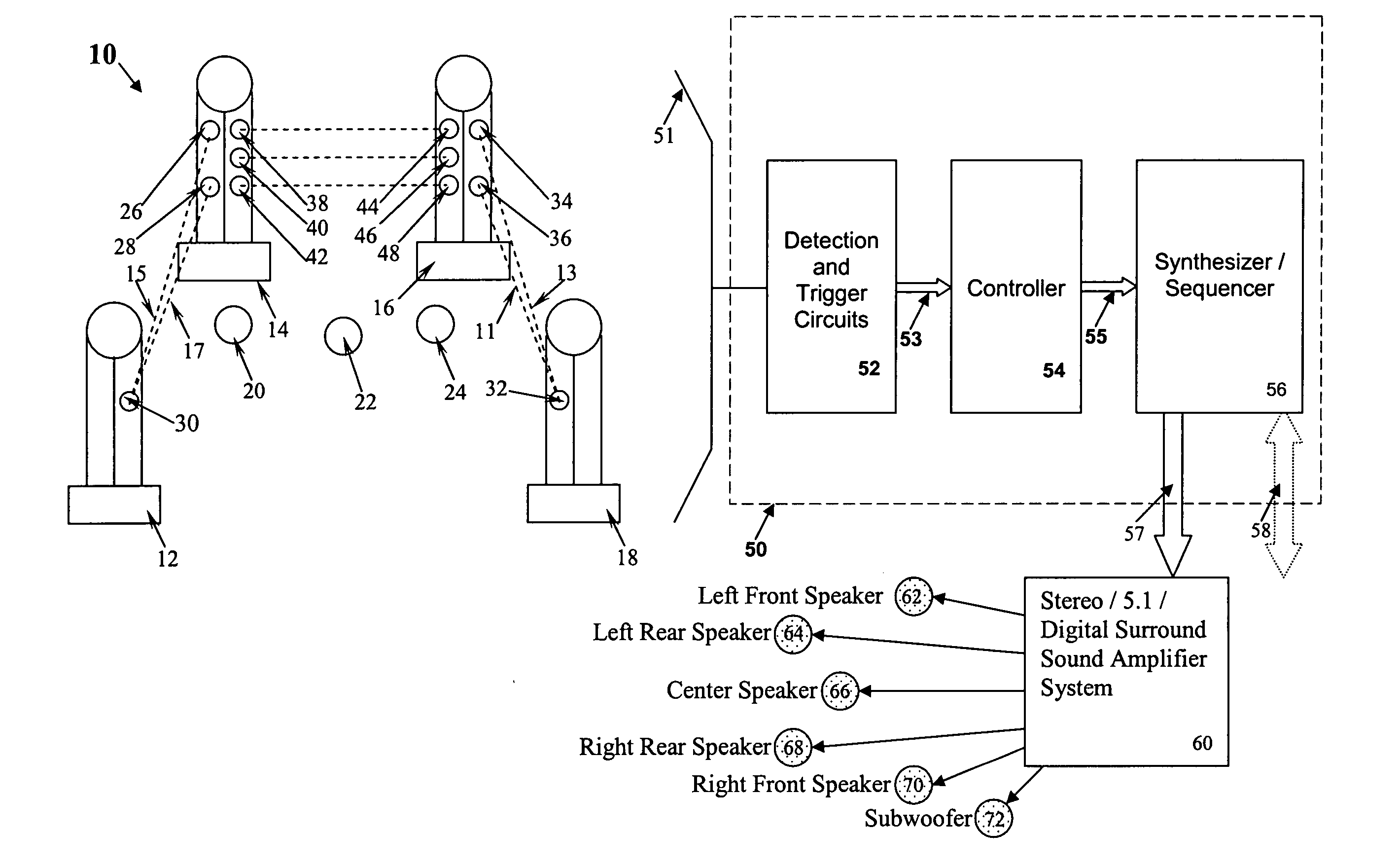
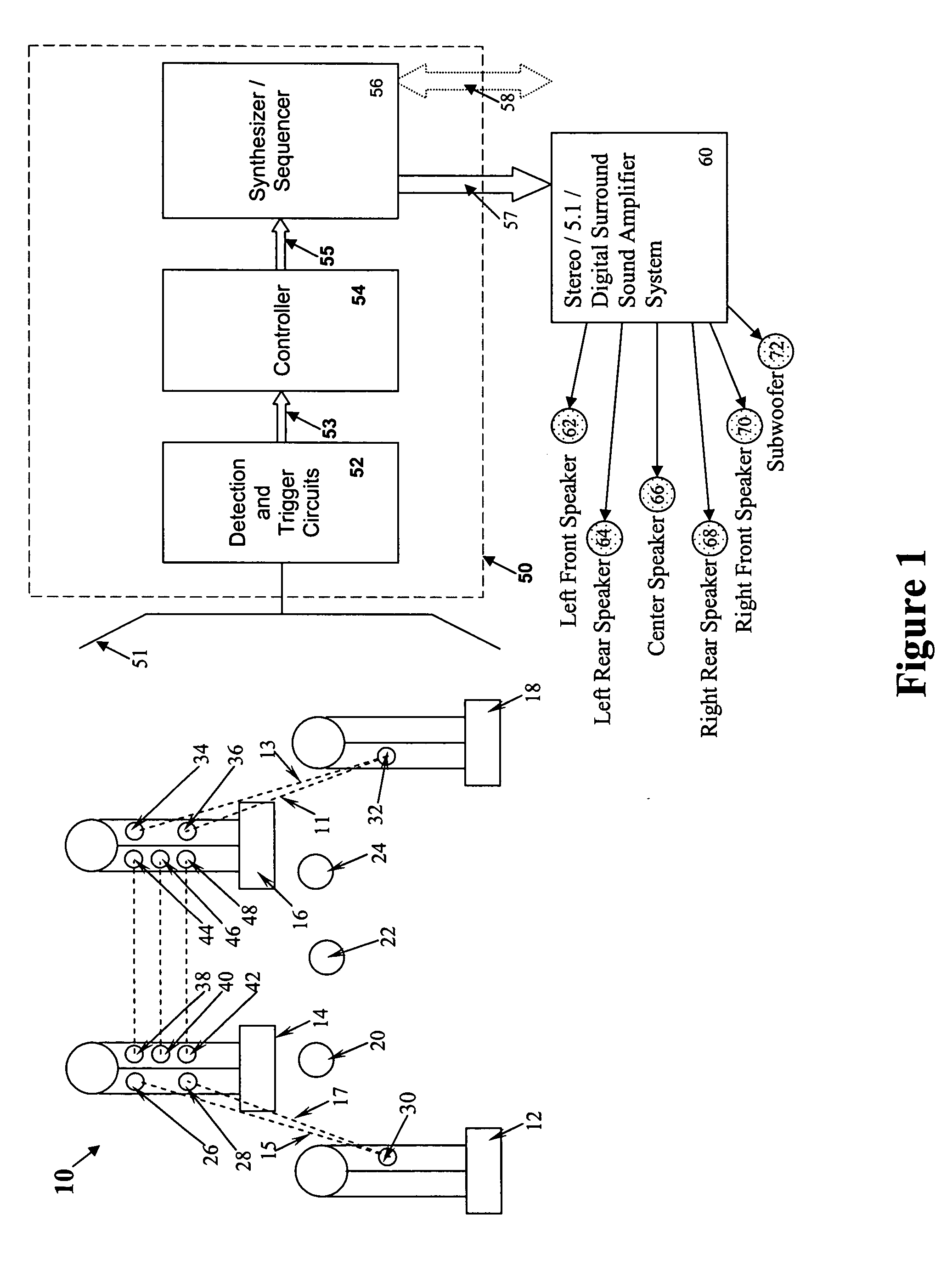
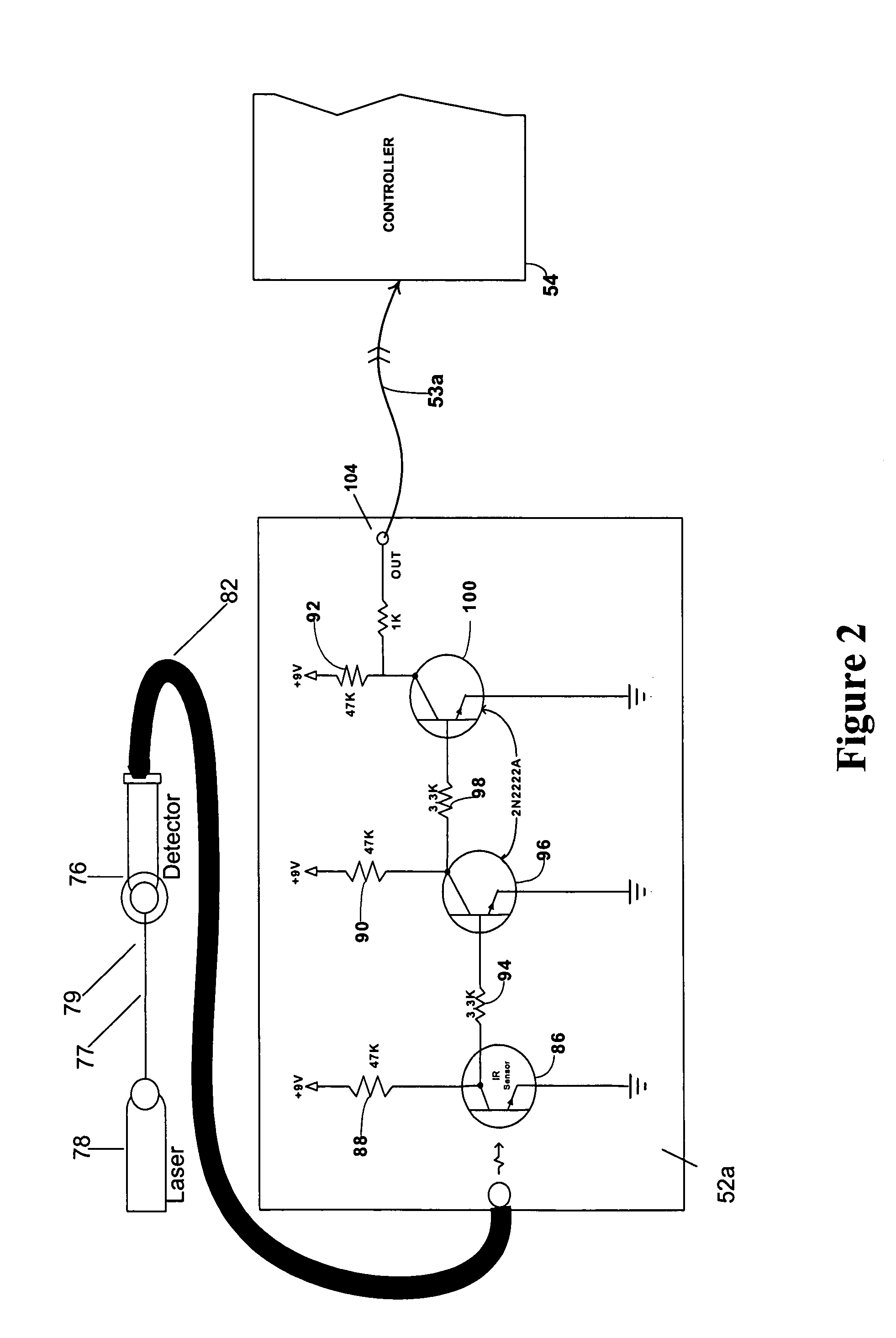
A system and methods which allow even a novice performer to easily play music which is not disharmonious and which is pleasing to the performer and his or her audience. The music is preferably created by a performer breaking one or more beams of light, which are emitted by one or more beam emitters and received, or detected, by one or more beam detectors. When a beam detector determines that a beam has been broken, a trigger is sent to a synthesizer, with such synthesizer preferably being a computer interfaced to the beam detectors via a Universal Serial Bus connection. The synthesizer selects from one or more electronic sounds, based on a pre-programmed collection of sounds, and a sound generator, such as an amplifier and speakers, plays the sound.

Description

PRIORITY CLAIM [0001] The instant application is a divisional of, and claims the benefit of, U.S. patent application Ser. No. 10 / 219,821 entitled “Music Instrument System and Method”, filed Aug. 16, 2002, which is related to and claims the benefit of U.S. Provisional Patent Application Ser. No. 60 / 312,843, filed Aug. 16, 2001, entitled “Music Instrument System and Method”. The teachings of these related applications are incorporated herein by reference in their entirety.FIELD OF THE INVENTION [0002] This invention relates to an instrument system for the composition and performance of sound data. More particularly, this invention relates to a system and method for an instrument which enables musical and other sound composition, and real-time creation and performance, utilizing an electronic instrument having sensor beam control, wherein the sound output, even when controlled by a novice performer, is pleasing and not disharmonious. BACKGROUND OF THE INVENTION [0003] There have been s...

Claims


Application Information

Patent Timeline
Patent Type & Authority Applications(United States)
IPC IPC(8): G10H1/00G10H1/20G10H1/34G10H1/44G10H7/00
CPCG10H1/00G10H1/0066G10H1/20G10H2210/371G10H2220/415G10H2240/321G10H2230/015G10H2240/061G10H2240/211G10H2240/255G10H2240/285G10H2220/421
Inventor RIOPELLE, GERALD HENRY
Owner TOPDOWN LICENSING LLC
Learn More