
Microfluidic apparatus and method for synthesis of molecular imaging probes

a molecular imaging and microfluidic technology, applied in the field of microfluidic devices and methods for chemical synthesis, to achieve the effect of promoting faster synthesis times and higher synthesis yields

Inactive Publication Date: 2005-10-20
MOLECULAR TECH
View PDF3 Cites 87 Cited by
  • Summary
  • Abstract
  • Description
  • Claims
  • Application Information

AI Technical Summary

Benefits of technology

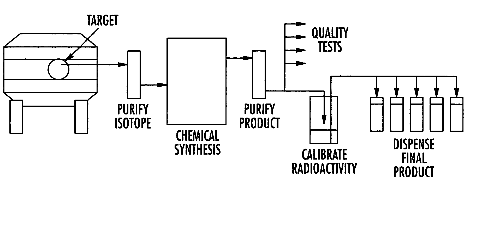
[0011] The present invention provides a method and apparatus for preparation of radiochemicals, such as PET molecular imaging probes, wherein the reaction step or steps that couple the radioactive isotope to an organic or inorganic compound to form a positron-emitting molecular imaging probe are performed in a microfluidic environment (i.e., a micro reactor). The reaction(s) to form the radiolabeled molecular imaging probes can utilize gaseous or liquid reagents in a liquid / liquid phase, liquid / gas phase or gas / gas phase reaction. The use of microfluidics and micro reactor technology for the radiochemical synthesis of labeled molecular imaging probes is advantageous because it matches the scale of the synthesis equipment and techniques to that of the radioactive labeling reagents, thereby promoting faster synthesis times, and higher synthesis yields. These systems are small, simple, reliable, microfluidics-based radiochemical synthesis systems.

Problems solved by technology

The same issues arise when using carbon-11 or other radioactive isotopes because the prior art radiochemical synthesis processes are the major source of unwanted carbon-12 or other stable isotopes.

Method used


Image

  • Microfluidic apparatus and method for synthesis of molecular imaging probes
  • Microfluidic apparatus and method for synthesis of molecular imaging probes
  • Microfluidic apparatus and method for synthesis of molecular imaging probes

Examples


example 1

Radiochemical Synthesis of [18F]fluoroethyl tosylate

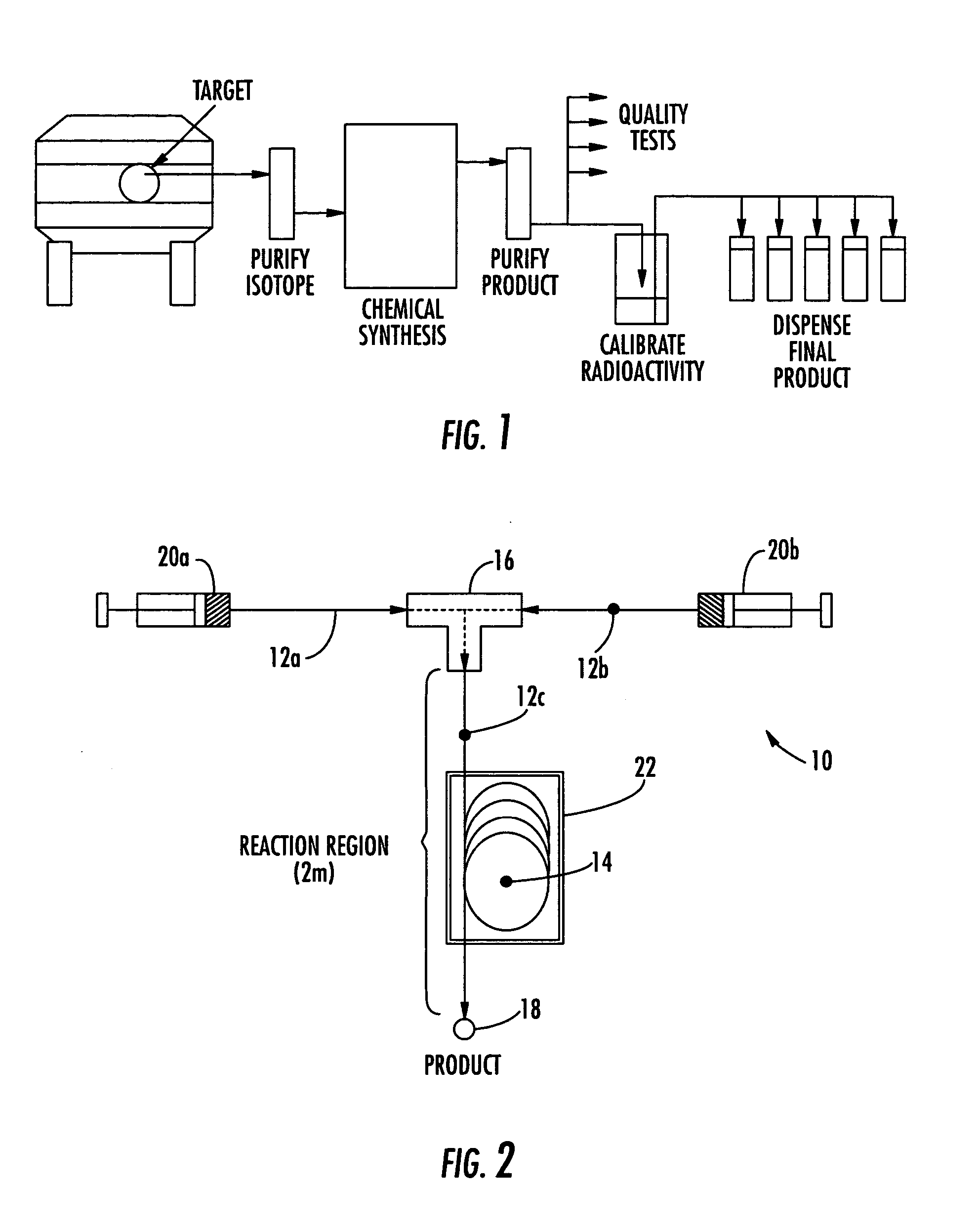
[0123] An embodiment of the micro reactor of the invention, which is shown in FIG. 2, was constructed using fused silica capillary tubing (360 μm OD×100 μm ID) and Microtight® fittings (Upchurch Scientific). Two pieces of capillary tubing exactly 25 cm long were attached to the opposite sides of a MicroTee (Part No. P-775, Upchurch Scientific, 150 μm thru-holes, 29 nL swept volume) and a third piece of capillary tubing 2 m long was attached to the remaining orthogonal position on the MicroTee. The chemical and radiochemical reagents were introduced into and moved through the reactor using a syringe pump (Harvard PHD 2000) and two 1 mL polypropylene syringes. A central 125 cm portion of the 2 m reaction channel was formed into four 10 cm diameter loops that were secured together. This section of four loops was placed in a water bath that was heated to 65-70° C. The output end of the reaction channel was placed into a small test tub...

example 2

Radiochemical synthesis of 2-deoxy-2-[18F]fluoro-1,3,4,6-tetra-O-acetyl-β-D-glucose

[0126] Using the same micro reactor apparatus described in Example 1 above, a solution of mannose triflate (4.4 mg, 9.2 μmol)) in acetonitrile (140 μL) was loaded into a 1 μL syringe. An anhydrous solution of [18F] fluoride ion (210 mCi) in 140 μL of acetonitrile (prepared as described in Example 1 above) was transferred to a second 1 μL syringe. Once the two syringes were loaded with equal volumes of reagent solution, the syringe pump was started at a flow rate of 4 μL / min. After 1 minute the flow rate was changed to 1.0 μL / min. The two solutions were pumped through the 2 m reaction channel that included the 125 cm portion heated to 65-70° C. over a period of 100 minutes. After about 100 minutes, the collected product solution was analyzed by radioTLC (silica gel, ether). In addition to unreacted [18F] fluoride ion at Rf=0.0, the desired radiofluorinated product was detected at Rf=0.65.

example 3

Radiochemical synthesis of 2-deoxy-2-[18F]fluoro-1,3,4,6-tetra-O-acetyl-β-D-glucose

[0127] [18F] fluoride ion in acetonitrile was prepared by the following method: [18O] water was irradiated with 11 MeV protons. At the end of bombardment the [18O] water was transferred through a Waters QMA Light anion exchange cartridge to trap the [18F] fluoride ion. The [18F] fluoride ion was then released from the resin column using 1.0 mL of potassium carbonate (5.5 mg) in a solution of 97.5% acetonitrile / 2.5% water by weight. This mixture was delivered in to a 20 mL glass vial where an additional 9 mL of dry acetonitrile was added. This resulted in a [18F] fluoride solution containing 0.25% water in acetonitrile by weight.

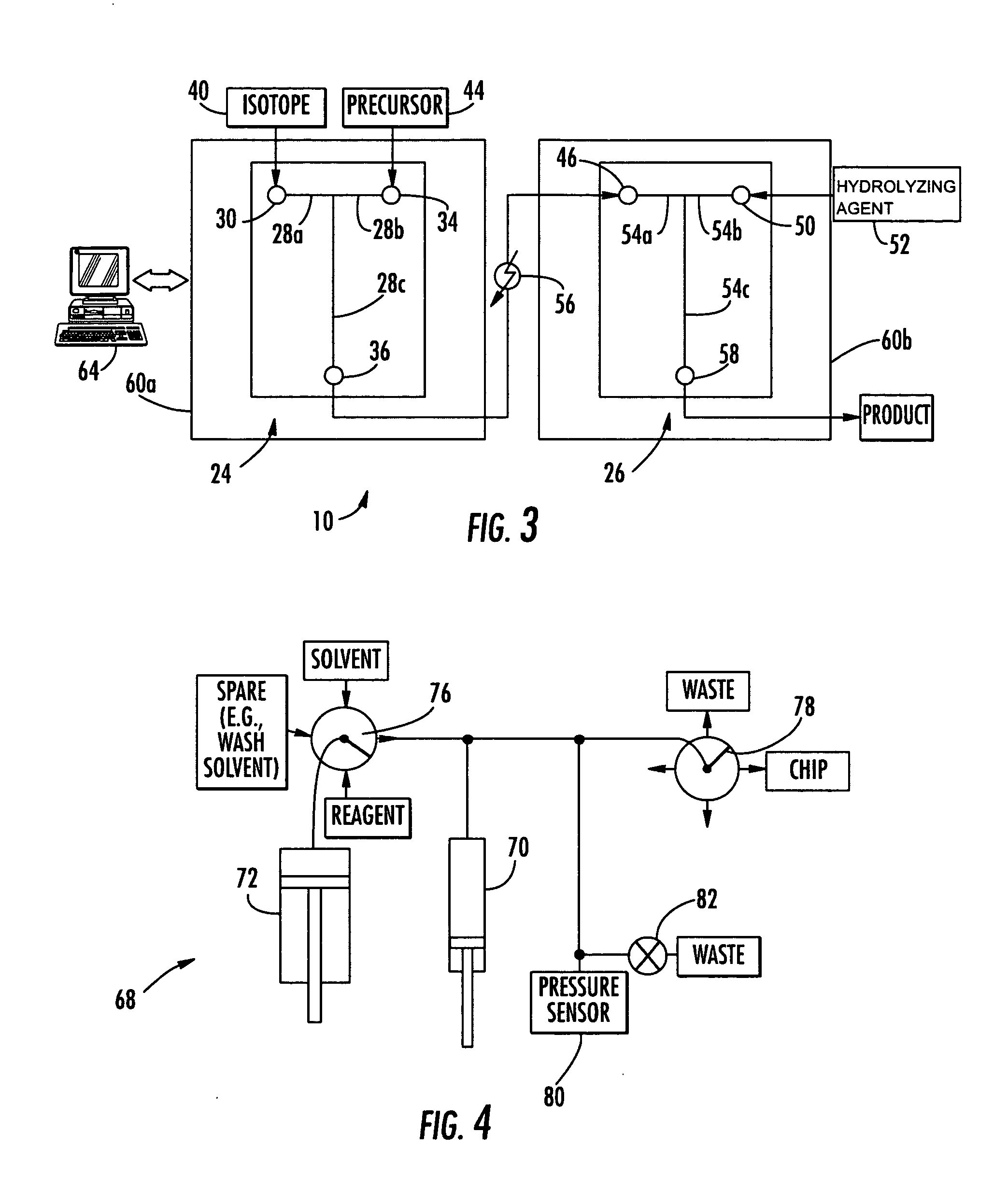
[0128] A micro reactor system was constructed using a microchip having a T-shaped microchannel with two inlet ports and an outlet port. Using a Hamilton Company, having an address of 4970 Energy Way, Reno, Nev. 89502, syringe system comprising SGE gas tight syringe needles, a...


PUM

PropertyMeasurementUnit
Temperatureaaaaaaaaaa
Fractionaaaaaaaaaa
Capacitanceaaaaaaaaaa

Abstract

The invention provides a method and apparatus for preparation of radiochemicals, such as PET molecular imaging probes, wherein the reaction step or steps that couple the radioactive isotope to an organic or inorganic compound to form a positron-emitting molecular imaging probe are performed in a microfluidic environment. The method for synthesizing a radiochemical in a microfluidic environment comprises: i) providing a micro reactor comprising a first inlet port, a second inlet port, an outlet port, and at least one microchannel in fluid communication with the first and second inlet ports and the outlet port; ii) introducing a reactive precursor into the first inlet port of the micro reactor, the reactive precursor adapted for reaction with a radioactive isotope to form a radiochemical; iii) introducing a solution comprising a radioactive isotope into the second inlet port of the micro reactor; iv) contacting the reactive precursor with the isotope-containing solution in the microchannel of the micro reactor; v) reacting the reactive precursor with the isotope-containing solution as the reactive precursor and isotope-containing solution flow through the microchannel of the micro reactor, the reacting step resulting in formation of a radiochemical; and vi) collecting the radiochemical from the outlet port of the micro reactor.

Description

BACKGROUND OF THE INVENTION [0001] 1. Field of the Invention [0002] The invention relates to the use of microfluidic devices and methods for chemical synthesis, particularly the use of microfluidic devices and methods for the synthesis of positron-emitter labeled PET molecular imaging probes. [0003] 2. Description of the Related Art [0004] Positron Emission Tomography (PET) is a molecular imaging technology that is increasingly used for detection of disease. PET imaging systems create images based on the distribution of positron-emitting isotopes in the tissue of a patient. The isotopes are typically administered to a patient by injection of probe molecules that comprise a positron-emitting isotope, such as F-18, C-11, N-13, or O-15, covalently attached to a molecule that is readily metabolized or localized in the body (e.g., glucose) or that chemically binds to receptor sites within the body. In some cases, the isotope is administered to the patient as an ionic solution or by inhal...

Claims


Application Information

Patent Timeline
IPC IPC(8): A61M36/14
CPCA61K51/0491
Inventor PADGETT, HENRY C.BUCHANAN, CHARLES RUSSELLCOLLIER, THOMAS LEEMATTEO, JOSEPH C.ALVORD, CHARLES W.
Owner MOLECULAR TECH
Learn More