Controller of ac generator for vehicle

a controller and ac generator technology, applied in the direction of electric generator control, dynamo-electric converter control, control system, etc., can solve the problems of generator not being miniaturized and quality reduction, and achieve the effect of reducing the conduction rate of the switching element, preventing the heating of the armature coil, and increasing the rotational speed

Inactive Publication Date: 2005-10-20
MITSUBISHI ELECTRIC CORP
View PDF21 Cites 13 Cited by
  • Summary
  • Abstract
  • Description
  • Claims
  • Application Information

AI Technical Summary

Benefits of technology

[0004] The present invention has been made to solve the above-mentioned problems, and it is an object of the present invention that after the rotational speed of the generator exceeds the predetermined value, an increase in output of the generator is suppressed, whereby it is possible to realize the miniaturized controller of an A.C. generator for vehicles (car, and the like) which is capable of preventing the heating of the armature coil, the rectifier and the like, and hence which requires no cooling fan.
[0005] A controller of an A.C. generator for vehicles according to the present invention includes: a switching element inserted in series in a field coil of an A.C. generator for intermittently controlling a field current supplied to the field coil in accordance with an output voltage from the A.C. generator in order to control the output voltage from the A.C. generator to a predetermined value; and conduction rate control means for detecting a rotational speed of the A.C. generator to reduce a conduction rate of the switching element in accordance with an increase in rotational speed.

Problems solved by technology

That is to say, there was encountered a problem such that temperatures of an armature coil and a rectifier rose along with an increase in output of the generator to become difficult to be suppressed within an allowable temperature, which resulted in reduction of quality.
In addition, there was encountered a problem that a large cooling fan was required as means for enhancing a cooling property in order to suppress rise of a temperature, which resulted in that a generator could not be miniaturized.

Method used


Image

  • Controller of ac generator for vehicle
  • Controller of ac generator for vehicle
  • Controller of ac generator for vehicle

Examples


embodiment 1

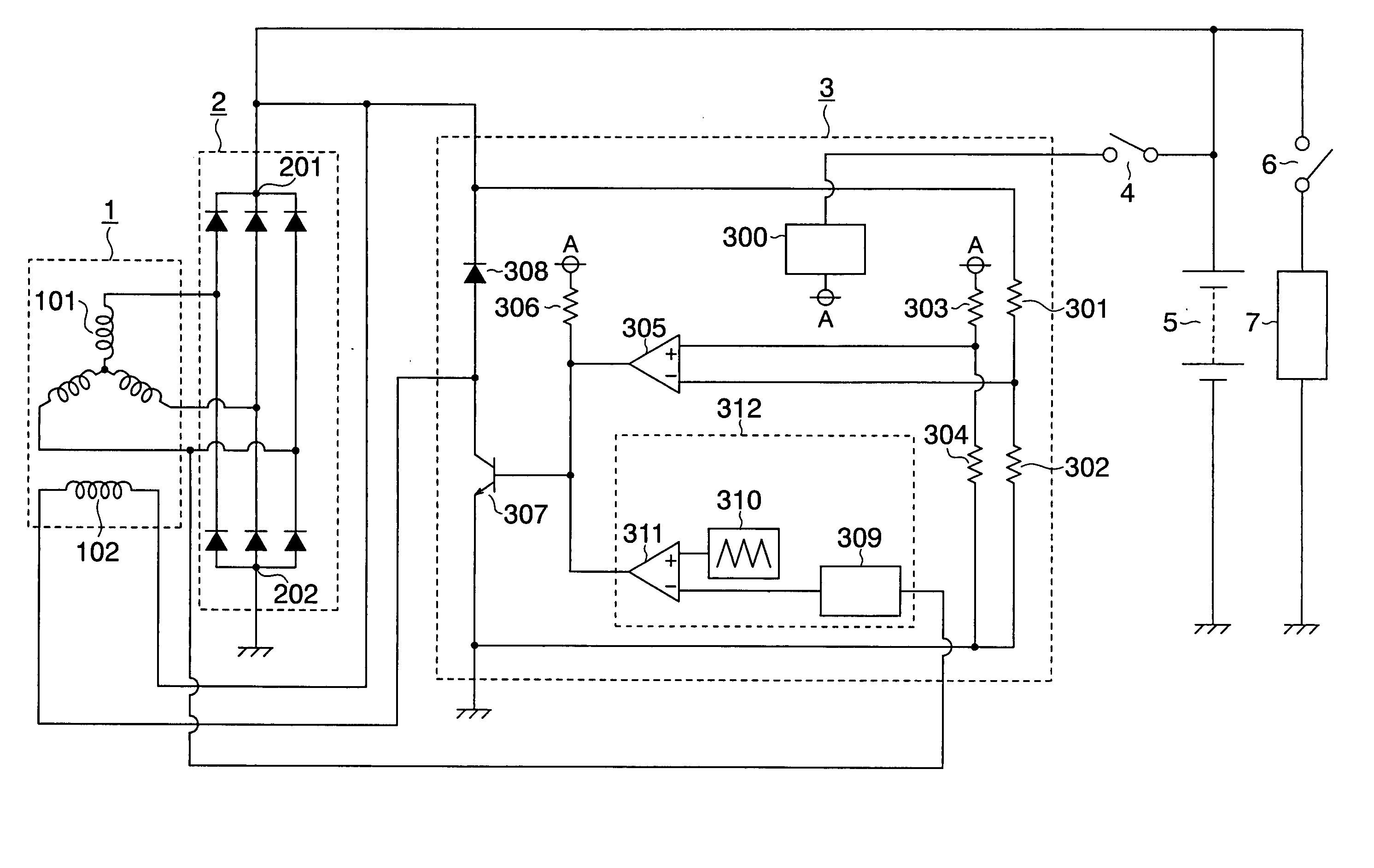
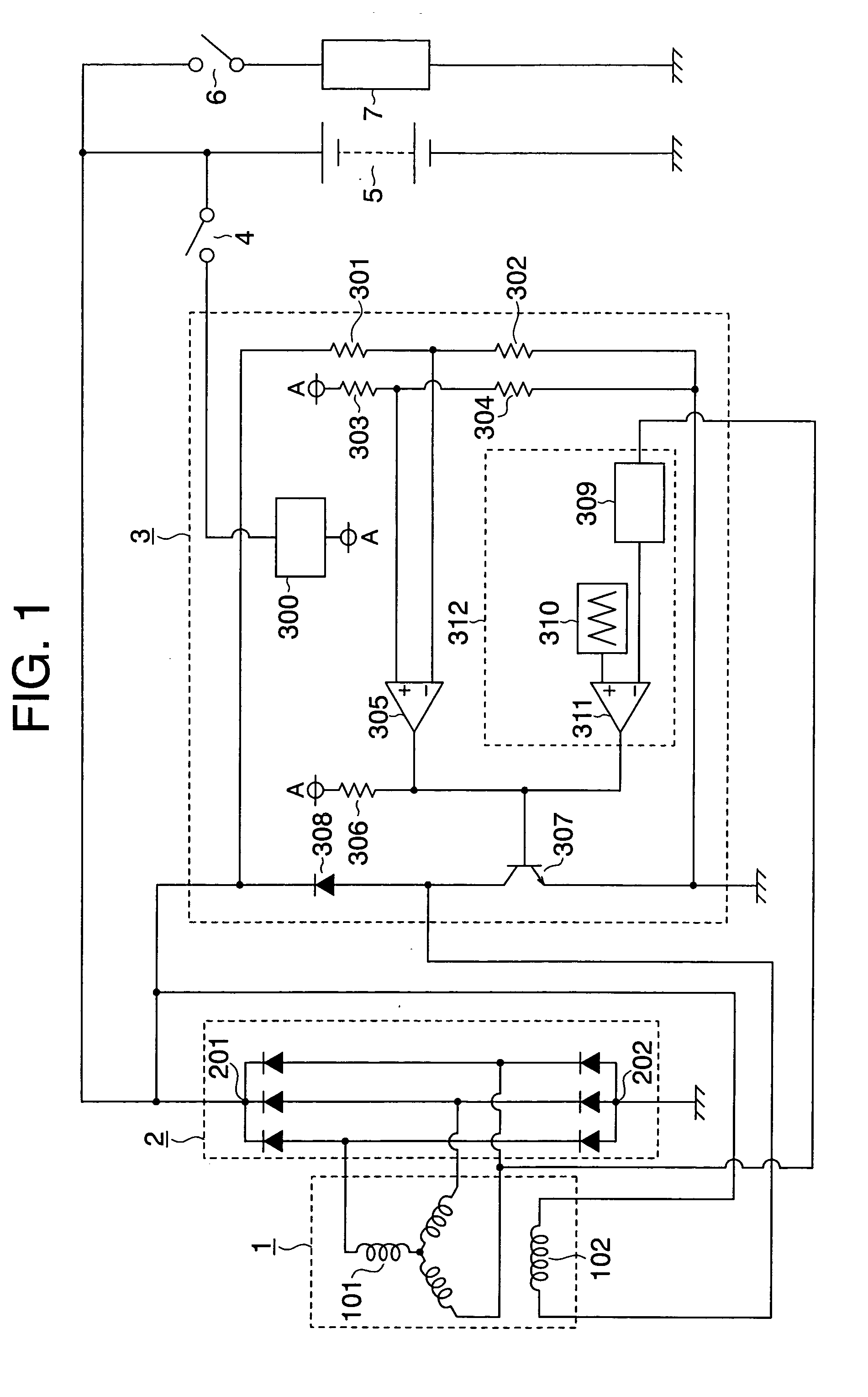
[0014]FIG. 1 is a circuit diagram of a controller of an A.C. generator for vehicles according to Embodiment 1 of the present invention. In FIG. 1, a generator for vehicles (hereinafter referred to as “a generator” for short when applicable) 1 which is to be driven by an engine (not shown) has an armature coil 101 and a field coil 102. A rectifier 2 for subjecting an A.C. output of the generator 1 to full wave rectification has a main output terminal 201 and a grounding terminal 202. In addition, a voltage regulator 3 for regulating an output voltage of the generator 1 to a predetermined value includes voltage division resistors 301 and 302 for detecting a voltage which serve to voltage-dividing an output voltage obtained through the main output terminal 201 of the rectifier 2 to detect a resultant voltage.

[0015] A constant voltage power supply circuit 300 provides a constant voltage source A on the basis of an electric power which is supplied from a battery 5 by turning ON a key sw...

embodiment 2

[0022] Next, FIG. 4 is a circuit diagram of a controller of an A.C. generator for vehicles according to Embodiment 2 of the present invention. The controller of Embodiment 2 has such a configuration as to newly provide a temperature detector 313 in the conduction rate control circuit 312 in addition to the constituent elements of the configuration shown in FIG. 1. FIGS. 5 to 7 show examples of concrete configurations of the above-mentioned temperature detector 313. FIG. 5 shows the temperature detector 313 including a thermosensitive semiconductor element, FIG. 6 shows the temperature detector 313 including a thermosensitive resistance element having a positive resistance temperature coefficient, and FIG. 7 shows the temperature detector 313 including a thermosensitive element having a negative resistance temperature coefficient.

[0023] The concrete configurations and operations of the temperature detectors 313 will hereinafter be described.

[0024] In FIG. 5, a diode 312a serving as...


PUM


Abstract

The structure of the present invention includes: a switching element inserted in series in a field coil of an A.C. generator for intermittently controlling a field current supplied to the field coil in accordance with an output voltage from the A.C. generator in order to control the output voltage from the A.C. generator to a predetermined value; and conduction rate control means for detecting a rotational speed of the A.C. generator to reduce a conduction rate of the switching element in accordance with an increase in rotational speed.

Description

TECHNICAL FIELD [0001] The present invention relates to a controller of an A.C. generator for vehicles. BACKGROUND ART [0002] A conventional controller of an A.C. generator for vehicles controlled a duty ratio of a switching element for intermittently controlling a field current of a generator to thereby limit the field current so as for the field current not to exceed a predetermined limitation value. Note that, the predetermined limitation value is selected so as to become a value equal to or larger than a value of a field current which is to be caused to flow in order to obtain a predetermined output from the generator when a temperature of a generator has risen up to a predetermined value (refer to JP 6-38720 B (page 2 and FIG. 1)). [0003] In accordance with such a conventional controller for an A.C. generator for vehicles, there are shown generator output characteristics in which a power transistor is usually held in a conduction state as long as a generated voltage is lower th...

Claims


Application Information

Patent Timeline
Patent Type & Authority Applications(United States)
IPC IPC(8): H02H7/06H02P9/00H02P9/30H02P11/00
CPCH02P9/305H02P9/30
Inventor IWATANI, SHIRO
Owner MITSUBISHI ELECTRIC CORP
Why Eureka
Try Eureka