
Tape carrier for TAB

a technology of tape carrier and tab, which is applied in the direction of cellulosic plastic layered products, transportation and packaging, chemistry apparatus and processes, etc., can solve the problems of insufficient satisfaction of demand, and achieve the effects of improving dimensional accuracy and positional accuracy, reducing weight, and thickness and siz

Inactive Publication Date: 2005-10-20
NITTO DENKO CORP
View PDF10 Cites 5 Cited by
  • Summary
  • Abstract
  • Description
  • Claims
  • Application Information

AI Technical Summary

Benefits of technology

[0010] The invention is developed upon such circumstances and an object of the invention is to provide a TAB tape carrier in which high-density wiring can be achieved while reduction in weight, thickness and size is attained as well as improvement in dimensional accuracy and positional accuracy in the TAB tape carrier can be achieved at the time of carrying the TAB tape carrier or at the time of mounting and bonding electronic parts.

Problems solved by technology

These demands cannot be satisfied sufficiently by the reinforcing effect of copper foil.

Method used


Image

  • Tape carrier for TAB
  • Tape carrier for TAB
  • Tape carrier for TAB

Examples


example 1

[0067] Stainless steel foil (SUS304, 250 mm wide) 20 μm thick was prepared as a reinforcing layer (see FIG. 4A). A solution of a polyamic acid resin was applied on the reinforcing layer, dried and heated to be cured to thereby form an insulating layer of a polyimide resin 12 μm thick (see FIG. 4B). Then, a chromium thin film and a copper thin film were formed successively on a front surface of the insulating layer by a sputtering vapor deposition method to thereby form an undercoat 2000 Å thick (see FIG. 4C).

[0068] Although FIGS. 4A and 5E show the form of one row of TAB tape carrier, Example 1 shows the case where four rows of 48 mm-wide TAB tape carriers are produced simultaneously on 250 mm-wide stainless steel foil.

[0069] Then, feeding holes were formed by punching so that each feeding hole pierced the reinforcing layer, the insulating layer and the undercoat in the direction of the thickness of the TAB tape carrier (see FIG. 4D). Then, a plating resist was formed as a predete...


PUM

PropertyMeasurementUnit
thicknessaaaaaaaaaa
widthaaaaaaaaaa
widthaaaaaaaaaa

Abstract

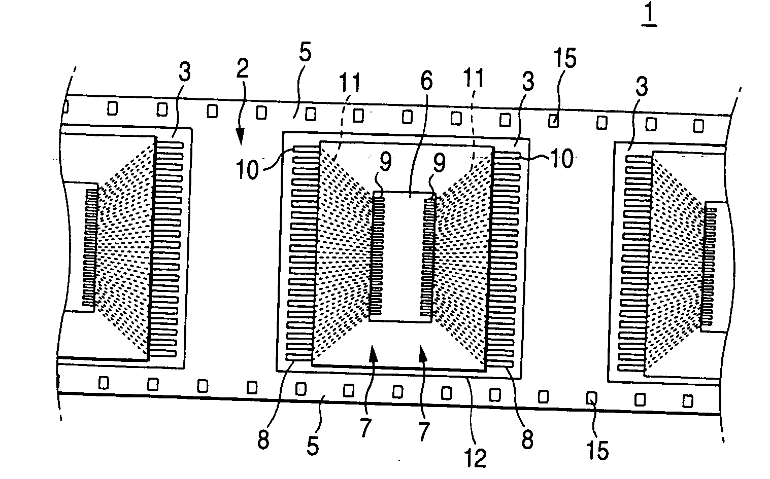
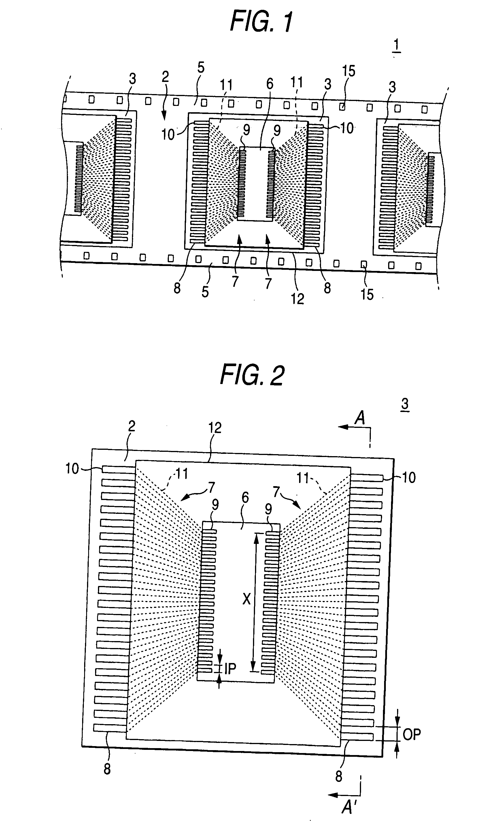
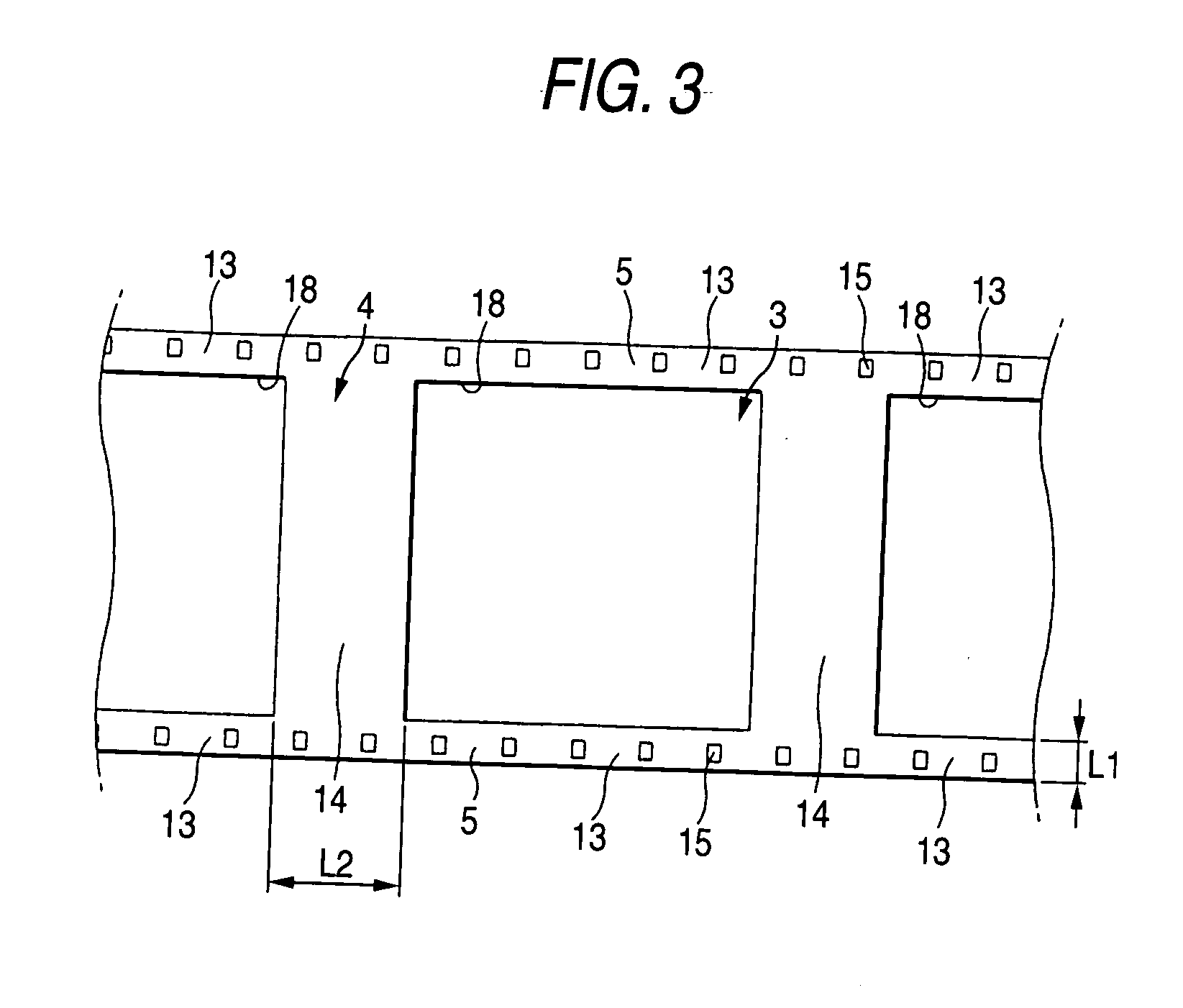
Electric conductor patterns having inner leads arranged at a pitch of not larger than 60 μm are formed on a front surface of an insulating layer of a tape carrier for TAB. A reinforcing layer of stainless steel foil is formed on a rear surface of the insulating layer so as to be extend along a lengthwise direction at opposite side edge portions in a widthwise direction of the insulating layer. Accordingly, both dimensional accuracy and positional accuracy can be improved at the time of carrying the tape carrier for TAB or at the time of mounting and bonding electronic parts though the insulating layer can be formed so as to be thin.

Description

BACKGROUND OF THE INVENTION [0001] 1. Field of the Invention [0002] The present invention relates to a tape carrier for TAB (hereinafter referred to as TAB tape carrier) and particularly to a TAB tape carrier for mounting electronic parts by a TAB method. [0003] 2. Related Art [0004] A TAB tape carrier is widely used for mounting electronic parts such as semiconductor devices by a TAB (Tape Automated Bonding) method. [0005][0006] A demand for reduction in weight, thickness and size of such a TAB tape carrier has been increasing with the advance of the demand for reduction in weight, thickness and size of electronic parts in recent years. [0007] On the other hand, such a TAB tape carrier is generally carried in the condition that sprockets are engaged with feeding holes formed along a lengthwise direction of the TAB tape carrier at opposite end portions in a widthwise direction of the TAB tape carrier so that a predetermined amount of tension is applied to the TAB tape carrier. For t...

Claims


Application Information

Patent Timeline
Patent Type & Authority Applications(United States)
IPC IPC(8): H01L23/12H01L21/60H01L23/495H01L23/498H01L23/50H01R43/00H05K1/00H05K3/00
CPCH01L23/49572H01L23/4985H05K1/0393H05K3/0097Y10T428/24777H05K2203/1545H01L2924/0002H05K2201/2009H01L2924/00H01L21/60
Inventor NAITO, TOSHIKIYAMAZAKI, HIROSHIOMOTE, TOSHIHIKO
Owner NITTO DENKO CORP
Learn More