
Magnetic recording medium, method for manufacturing recording medium and magnetic recording apparatus

a technology of magnetic recording and recording media, which is applied in the field of magnetic recording media, methods for manufacturing recording media and magnetic recording apparatus, can solve the problems of large noise influence on inability to control the crystalline grains of the magnetic layer and the under-layer, and large noise signals at the boundary regions between recording bits. to achieve the effect of increasing the signal to noise ratio and high density recording

Active Publication Date: 2005-09-29
KK TOSHIBA
View PDF4 Cites 9 Cited by
  • Summary
  • Abstract
  • Description
  • Claims
  • Application Information

AI Technical Summary

Benefits of technology

[0011] The present invention is directed to give a solution to the problems. The purpose of the present invention is to present a novel magnetic recording medium having excellent recording signal resolution and signal to noise ratio (SNR) realizing small average grain diameter dispersion, methods for manufacturing the magnetic recording medium, and magnetic recording apparatus equipped with the recording medium.
[0016] The present invention has a remarkable advantage in the point that the crystalline grain size of the grain diameter control under-layer comprising crystalline grains is not needed to be small for obtaining small magnetic crystalline grains. The problem of employing small grain size under-layers, therefore, can be avoided to obtain small magnetic grains. The present invention presents a novel means for obtaining magnetic recording medium having increased recording and reproducing characteristics.
[0022] The present invention provides a novel means for obtaining magnetic layer having very small magnetic crystalline grains and magnetic recording media for high density recording having increased signal to noise ratio.

Problems solved by technology

Furthermore, noise signals which appear at boundary regions between recording bits became large as a result of decreasing recording bits to a very small size, and the noise gave large influences upon-the signal to noise ratio.
These methods, however, cannot control the crystalline grains of the magnetic-layer and the under-layer by going back to the nucleation processes for the crystalline grains of the under-layer and the magnetic recording layer.
Magnetic recording media decreasing the average grain size of the magnetic crystalline grains to 5 nm showed poor thermal fluctuation durability.
Then it was difficult to attain further high density using this method.

Method used


Image

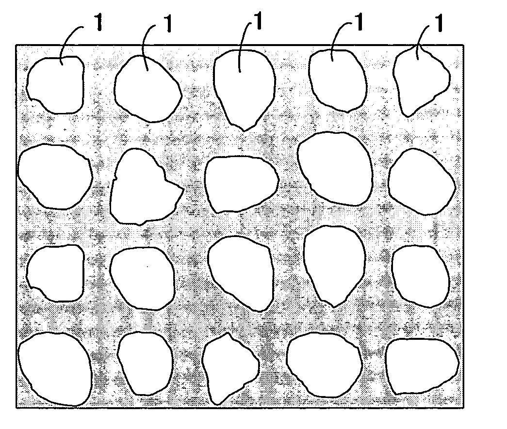
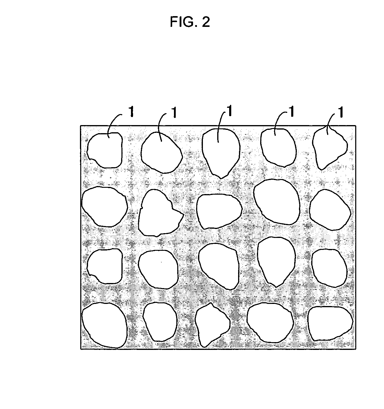
  • Magnetic recording medium, method for manufacturing recording medium and magnetic recording apparatus
  • Magnetic recording medium, method for manufacturing recording medium and magnetic recording apparatus
  • Magnetic recording medium, method for manufacturing recording medium and magnetic recording apparatus

Examples


example 1

[0072] Nonmagnetic 2.5 inches glass substrates were put into a vacuum chamber of an ANELVA Co. c-301 type sputtering apparatus. The vacuum chambers of the sputtering apparatus were evacuated to 1×10⁻⁶ Pa or less.

[0073] Then substrates were heated using an infrared heater up to about 300° C. Keeping the substrate temperature to about 300° C., about 200nm CoZrNb film was deposited as a soft magnetic under-layer, and then an about 30 nm Ni film was deposited to each substrate.

[0074] Each substrate was then elevated to about 500° C, and exposed to oxide or ethylene atmosphere in a range of 1×10⁻⁵ to 1×10⁻² Pa. After the oxide or ethylene exposure, a 5 nm thick Fe50Pt50 film was deposited as a magnetic recording layer.

[0075] Then a 5 nm carbon film was deposited. For the deposition of CoZrNb, Ni, Fe50Pt50 and C films, the Ar gas pressure was controlled to 0.7 Pa, 0.7 Pa, 5 Pa and 0.7 Pa, respectively, and as the target material, CoZrNb, Ni, Fe50Pt50, and C, respectively was used. DC s...

example 2

[0091] Nonmagnetic 2.5 inches glass substrates were put into the vacuum chambers and the vacuum chambers were evacuated to 1×10⁻⁶ Pa or less. Then CoZrNb soft under-layer, Cu, Ni, Rh and Pt films were deposited respectively, using the method described in Example 1.

[0092] Oxygen deposited layer was formed irradiating oxygen ions at 200 eV using ion gun on the under-layer surface in oxygen atmosphere in a range from 1×10⁻⁵ Pa to 1×10⁻² Pa. Then magnetic recording layer of a 5 nm Co70Cr10Pt20−TiN was formed using Co70Cr10Pt20-10 mol % TiN composite target. Magnetic recording layers replacing Co70Cr10Pt20 by Fe50—Pt50, Co50Pt50 and Co50Pd50, and replacing TiN by AlN, TaN, TiC and TaC were deposited respectively. Using similar procedure as described in Example 1, carbon protective layer was deposited and lubricant layer was coated. Then, various magnetic recording media were prepared.

[0093] Table 2A and 2B show SNRm values and dPW50 values for each magnetic recording medium. Magnetic r...

example 3

[0095] Nonmagnetic 2.5 inches glass substrates were put into the vacuum chambers and the vacuum chambers were evacuated to 2×10⁻⁶ Pa or less. Then on the CoZrNb soft under-layer, Cu, Ni, Rh or Pt film was deposited, and then deposited carbon layer was formed using the method described in example 1 to each substrate. Magnetic recording layer of a 5 nm Co70Cr10Pt20—SiO2 was formed using 5 nm Co70Cr10Pt20-10 mol % SiO2 composite target. Magnetic recording layers replacing Co70Cr10Pt20 by Fe50—Pt50, Co50Pt50 and Fe50Pd50, and replacing SiO2 by TiO, Al2O3, TiN, AlN, and TaN, were deposited respectively. Using similar procedure described in Example 1, carbon protective layer was deposited and lubricant layer was coated. Then, various magnetic recording media were prepared.

[0096] Table 3A and 3B show SNRm values and dPW50 values for each magnetic recording medium. Magnetic recording layer structure composite with chemical compound leads desirably increased magnetic recording medium SNRm. ...


PUM

PropertyMeasurementUnit
grain diameteraaaaaaaaaa
grain sizeaaaaaaaaaa
grain diameteraaaaaaaaaa

Abstract

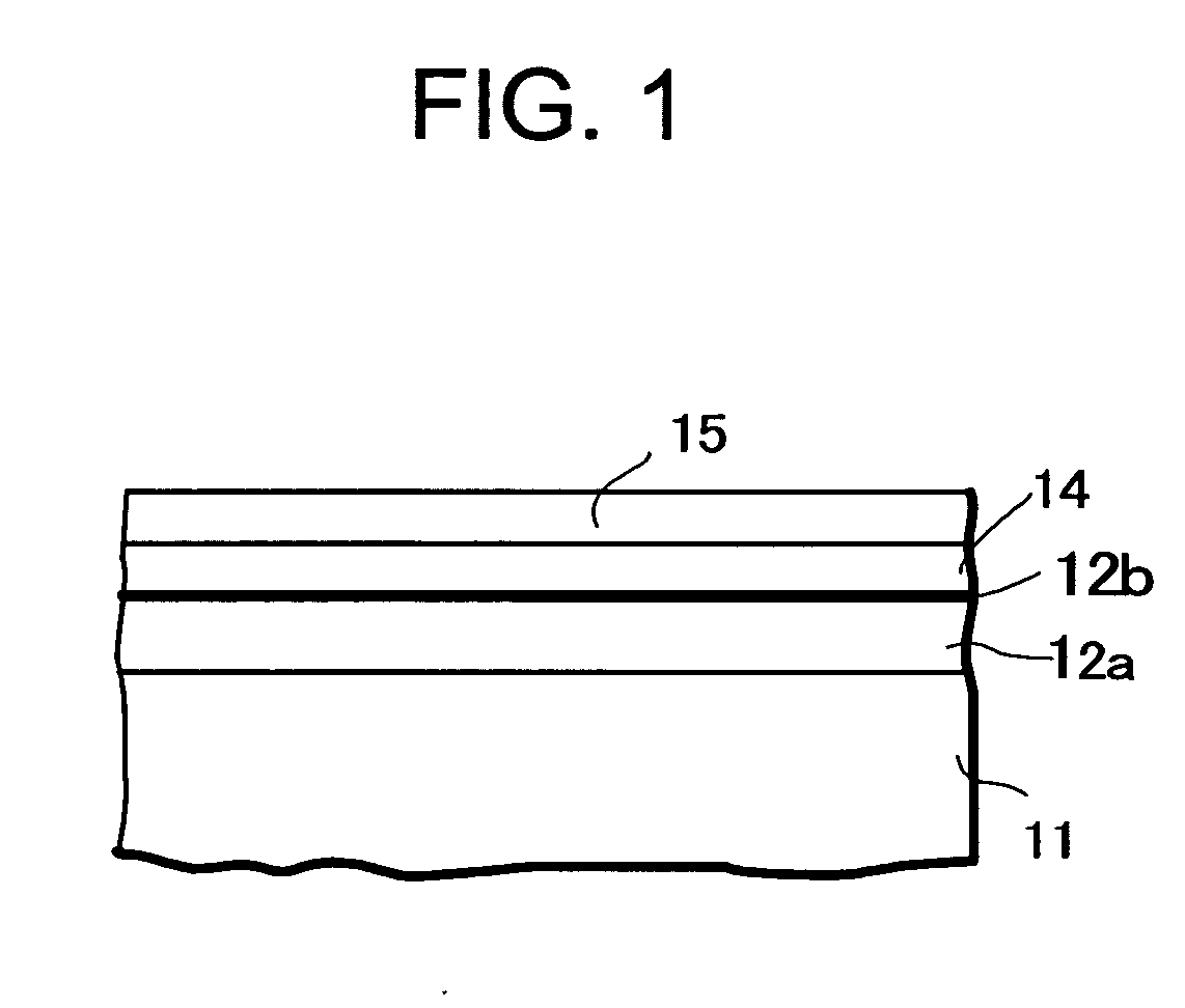
A grain diameter controlling crystalline layer comprising crystalline grains of a metal selected from the group consisting essentially of Cu, Ni, Rh and Pt was formed on a substrate. Then, deposited atom layer of at least one element selected from the group consisting of oxygen and carbon was formed on the surface of the grain diameter control layer. A magnetic recording layer was deposited on the atoms deposited grain diameter controlling crystalline layer. Then a magnetic recording medium in which the magnetic crystalline grains has small grain diameter and small grain diameter distribution, and the magnetic recording medium shows increased signal to noise ratio at high recording density.

Description

CROSS-REFERENCE TO RELATED APPLICATIONS [0001] This application is based upon and claims the benefit of priority from the prior Japanese Patent Application No. 2004-090670, filed on Mar. 25, 2004; the entire contents of which are incorporated herein by reference. BACKGROUND OF THE INVENTION [0002] 1. Field of the Invention [0003] The present invention relates to magnetic recording media, methods for manufacturing recording media and a magnetic recording apparatus, in particular, to magnetic recording media having high recording density, methods for manufacturing the recording media and magnetic recording apparatus such as hard disk drives in which the high-density recording media are equipped. [0004] 2. Description of the Related Art [0005] Hard disk drives (HDDs) have been expanding their application scope from the first computer related application to various other applications, such as home video recorder and car carrying navigation system applications as magnetic recording syste...

Claims


Application Information

Patent Timeline
Patent Type & Authority Applications(United States)
IPC IPC(8): G11B5/738G11B5/64G11B5/65G11B5/66G11B5/667G11B5/73G11B5/84H01F10/16
CPCG11B5/65G11B5/7325G11B5/667G11B5/737G11B5/657
Inventor MAEDA, TOMOYUKIKIKITSU, AKIRAOIKAWA, SOICHIIWASAKI, TAKESHI
Owner KK TOSHIBA
Learn More