Eureka AIR delivers breakthrough ideas for toughest innovation challenges, trusted by R&D personnel around the world.

Honeycomb structural body

a technology of honeycomb and structural body, applied in the direction of metal/metal-oxide/metal-hydroxide catalyst, machine/engine, chemical/physical process, etc., can solve the problems of obstructing ventilation, brittleness, environmental damage, etc., and achieve the effect of reducing the viscosity of raw material paste in a certain rang

Inactive Publication Date: 2005-09-29
IBIDEN CO LTD
View PDF16 Cites 71 Cited by
  • Summary
  • Abstract
  • Description
  • Claims
  • Application Information

AI Technical Summary

Benefits of technology

[0098] The compounding amount of such amorphous silicon powder is appropriately changed in accordance with the particle size, shape and the like of the ceramic particle powder, but is desirable to be 5-50 parts by weight based on 100 parts by weigh of the mixed powder. When the amount is less than 5 parts by weight, the compounding amount of the amorphous silicon powder is too small for sufficiently functioning as the bonding material bonding the ceramic particles, and the strength of the resulting honeycomb structural body (ceramic block) may be insufficient. On the other hand, when it exceeds 50 parts by weight, the resulting honeycomb structural body becomes too densified to lower the porosity and the aforementioned effects of the invention can not be sufficiently obtained. Further, when the honeycomb structural body of the invention is used as the honeycomb filter, there is a fear that the pressure loss in the catching of particulates quickly increases and the function as the filter can not sufficiently obtained.
[0099] As the binder are used, for instance, methyl cellulose, carboxymethyl cellulose, hydroxyethyl cellulose, polyethylene glycol, phenolic resin, epoxy resin and the like.
[0100] The compounding amount of the binder is desirable to be about 1-10 parts by weight based on 100 parts by weight of ceramic particle powder.
[0101] The dispersion medium is not particularly limited, and includes, for example, an organic solvent such as benzene or the like; an alcohol such as methanol or the like, water and so on.
[0102] The dispersion medium solution is compounded in a proper amount so as to render the viscosity of the raw material paste into a certain range.
[0103] These mixed powder, binder and dispersion medium are mixed by an attritor or the like and fully kneaded by a kneader or the like to form a raw material paste, and thereafter the raw material paste is extrusion molded to prepare the ceramic molded body.

Problems solved by technology

Recently, it has become a problem that particulates contained in the exhaust gas discharged from the internal-combustion engine in vehicles such as buses, trucks and the like, or construction machines have caused much harm to environment and the human body.
With such a purification of the exhaust gas, the particulates are gradually accumulated at the portions of the partition walls separating the through-holes of the honeycomb filter to cause the clogging to thereby obstruct ventilation.
In the above honeycomb filter, therefore, it is required to conduct regeneration treatment by regularly burning and removing the particulates as a cause of clogging with the use of a heating means such as a heater or the like.
However, the honeycomb filter disclosed in JP-A-6-182228 has a problem of becoming brittle and lowering compression strength if the porosity is raised.
Therefore, the above honeycomb filter has a tendency that it becomes easily breakable by compression load added in case of setting within a casing through the above-described holding sealing material, and the setting within the casing becomes difficult.
Furthermore, the above honeycomb filter is used by successively repeating the treatments such as catching and regeneration, so that it is subjected to thermal stress, and there is a problem that if such a thermal stress is applied, the ceramic particles themselves are broken between the ceramic particles to cause visualable size cracks.
Therefore, in case of making the porosity of the honeycomb structural body high, the compression strength is somewhat improved as compared with the honeycomb filter disclosed in JP-A-6-182228, but no improvement by a large margin can be recognized, and there is a problem of breaking by compression load added when setting within the casing.
Since the above honeycomb filter is also used by successively repeating the treatments such as catching and regeneration, so that it is subjected to thermal stress, and there is a problem that if such a thermal stress is applied, fine cracks hardly confirmed visually but confirmable by the observation through SEM are caused in silicon at the bonding portion between the ceramic particles, and as such fine cracks grow, the ceramic particles are broken between the ceramic particles to cause visualable size cracks or removal of the particles.
However, since the above vitreous oxide changes to be crystalline at a low temperature as compared with metal silicon, there is a problem that when the honeycomb structural body is heated to a high temperature in the regeneration treatment or the like, the vitreous oxide is crystallized to lower the strength of the honeycomb structural body itself, and the structural body is broken by a pressure of the exhaust gas flowed therein.

Method used


Image

  • Honeycomb structural body
  • Honeycomb structural body
  • Honeycomb structural body

Examples


example 1

[0144] (1) At first, a thin film of amorphous silicon is made by a chemical vapor deposition method (plasma CVD method) using silane (SiH4) and then the thin film is finely pulverized to obtain amorphous silicon powder having a mean particle size of 5 μm (half-width value of Si peak (2θ=about 28°) in an X-ray diffraction measured by the following method is 5.0°).

[0145] 20 wt % of the amorphous silicon powder and 80 wt % of α-type silicon carbide powder having a mean particle size of 30 μm are wet-mixed, and to 100 parts by weight of the thus obtained mixed powder are added and kneaded 6 parts by weight of a binder (methyl cellulose), 2.4 parts by weight of a surfactant (oleic acid) and 24 parts by weight of water to prepare a raw material paste.

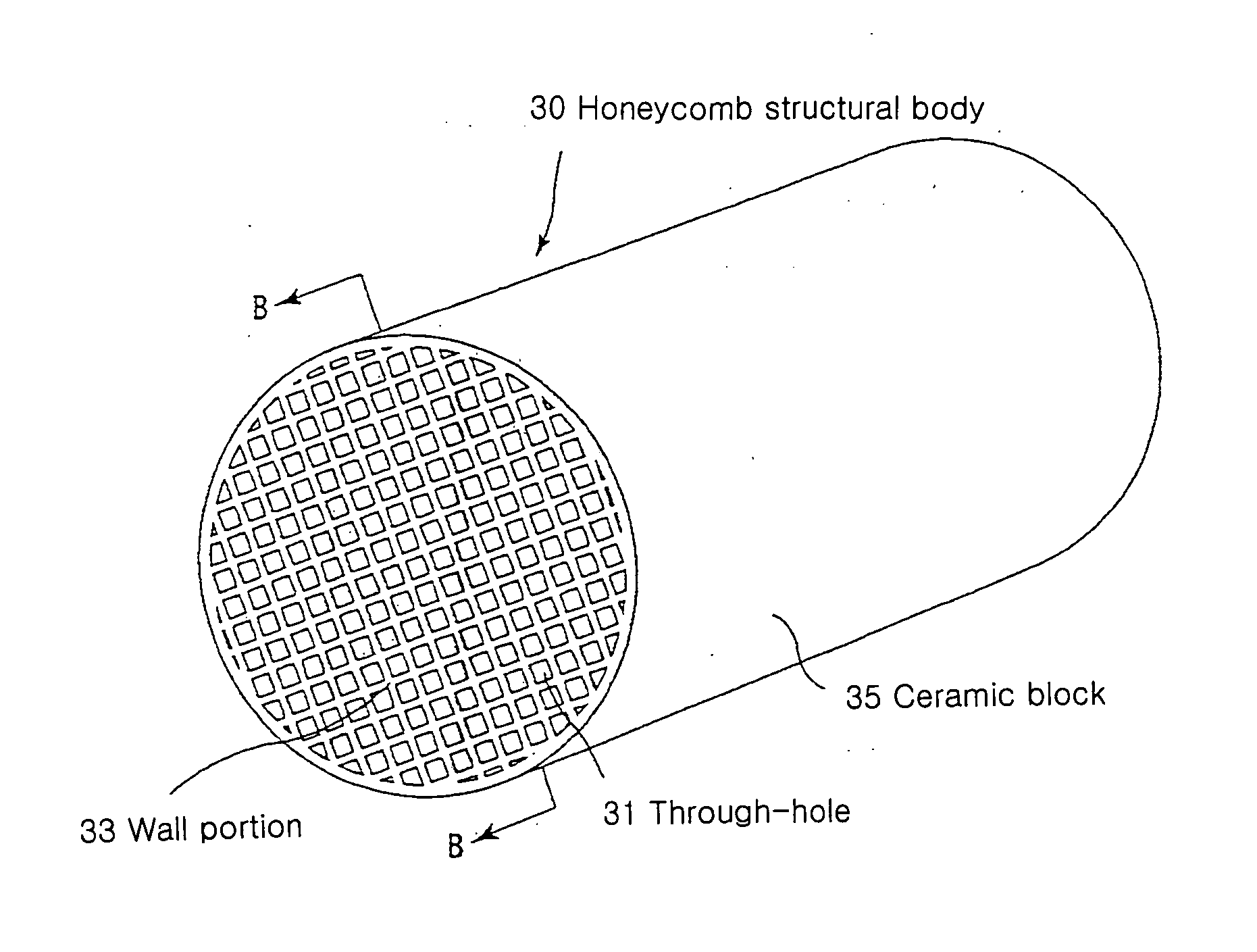
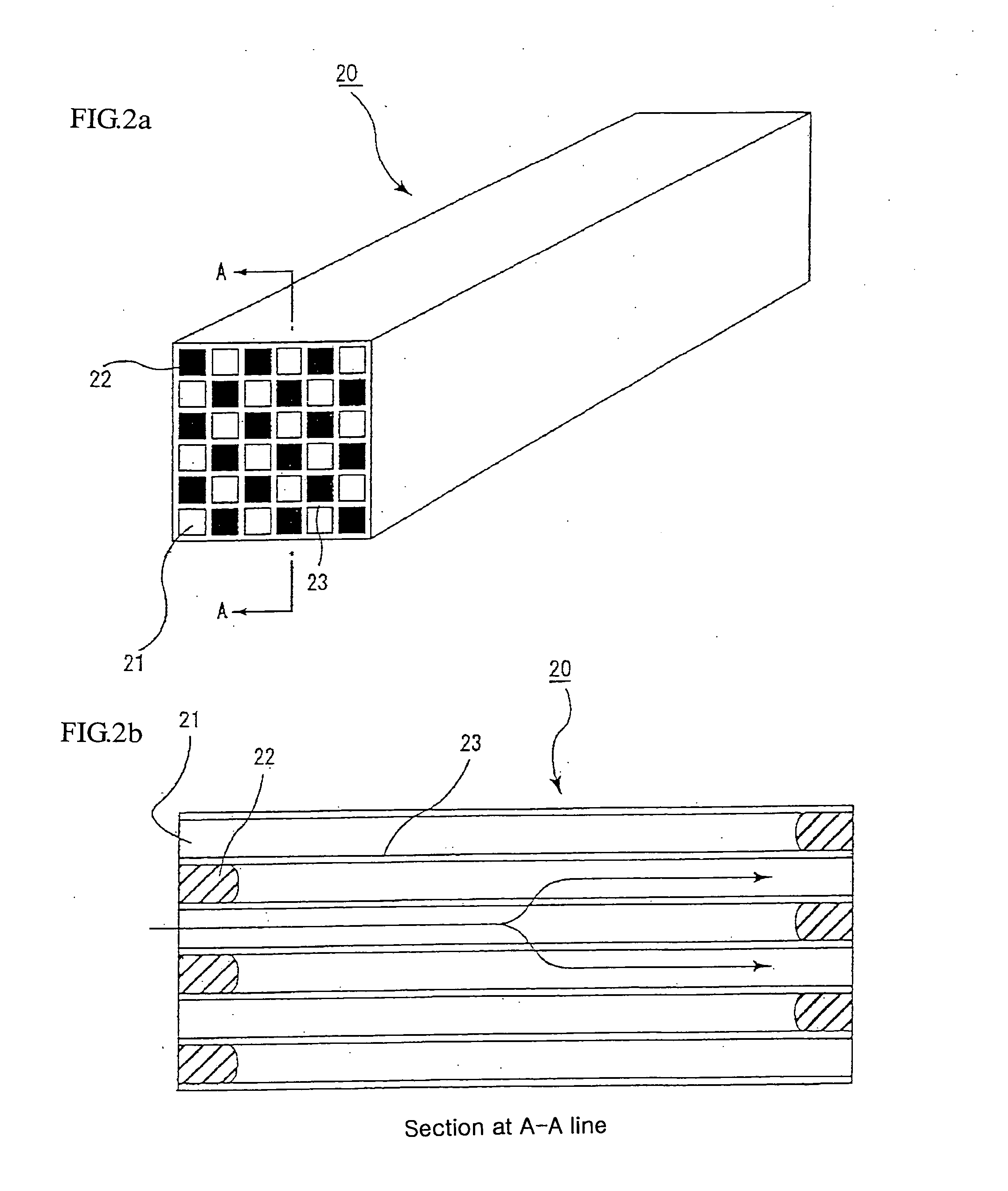
[0146] Next, the raw material paste is filled in an extruder and extruded at a rate of 10 cm / min to prepare a green shaped body having substantially the same shape as that of the porous ceramic member 30 shown in FIG. 2.

[0147] Then, the gr...

example 2

[0153] (1) A porous ceramic member is produced in the same manner as in Example 1(1) except that the firing condition in the bonding of silicon carbide particles with amorphous silicon is 1000° C. and 1 hour.

[0154] (2) A honeycomb structural body to be functioned as a honeycomb filter for purifying an exhaust gas is produced in the same manner as in Example 1(2) except for the use of the porous ceramic member produced in the above item (1).

example 3

[0155] (1) A porous ceramic member is produced in the same manner as in Example 1(1) except that the firing condition after the bonding of silicon carbide particles with amorphous silicon is 1000° C. and 30 minutes.

[0156] (2) A honeycomb structural body to be functioned as a honeycomb filter for purifying an exhaust gas is produced in the same manner as in Example 1(2) except for the use of the porous ceramic member produced in the above item (1).


PUM

PropertyMeasurementUnit
Angleaaaaaaaaaa
Angleaaaaaaaaaa
Lengthaaaaaaaaaa

Abstract

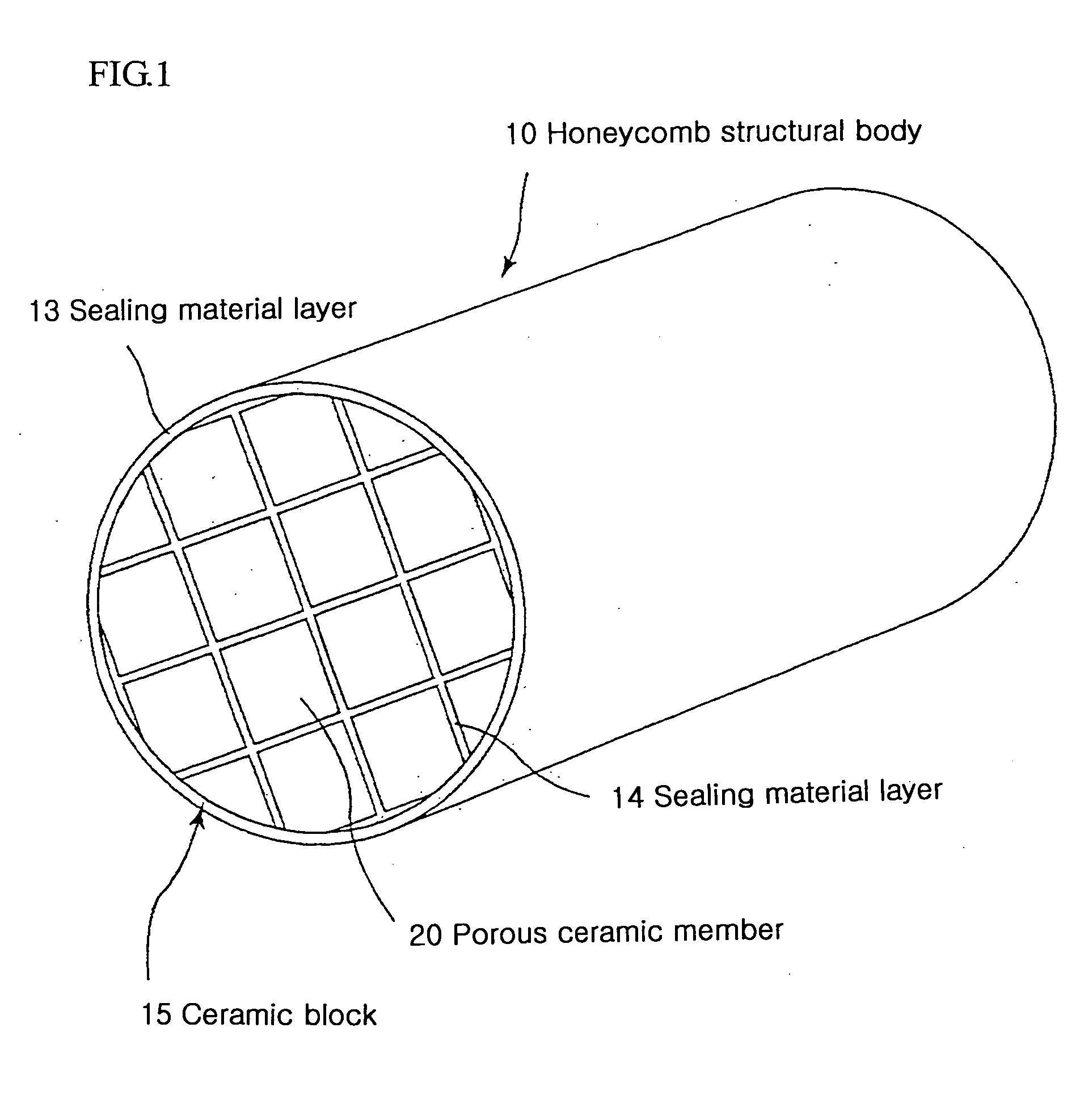
A honeycomb structural body is constituted with a ceramic block made by arranging a plurality of through-holes side by side in the longitudinal direction through partition walls and sealing either one end portions of these through-holes. The ceramic block of this honeycomb structural body is made of a composite member consisting of ceramic particles and amorphous silicon, so that the honeycomb structural body has an excellent compression strength even if its porosity is increased, and is less in the lowering of mechanical strength even if it is heated to a high temperature, and is excellent in the durability.

Description

RELATED APPLICATION [0001] This application is an application claiming a priority right based on Japanese Patent Application of 2002-293691 filed on Oct. 7, 2002.TECHNICAL FIELD [0002] The present invention relates to a honeycomb structural body used as a filter, a catalyst carrier or the like for removing particulates and the like in an exhaust gas discharged from an internal-combustion engine such as a diesel engine or the like. BACKGROUND ART [0003] Recently, it has become a problem that particulates contained in the exhaust gas discharged from the internal-combustion engine in vehicles such as buses, trucks and the like, or construction machines have caused much harm to environment and the human body. [0004] There are proposed various filters wherein the exhaust gas is passed through a porous ceramic to catch particulates in the exhaust gas and purify the exhaust gas. [0005] As such a ceramic filter, there has been known a honeycomb filter constituted that a plurality of through...

Claims


Application Information

Patent Timeline
IPC IPC(8): B01D39/20B01D46/00B01D46/24B01D53/86B01D53/88B01D53/94B01J35/04B28B11/00C04B35/117C04B35/638C04B38/00F01N3/022F01N3/28
CPCB01D39/2079Y10T428/24157B01D46/2418B01D46/4218B01D53/8653B01D53/885B01D53/9454B01J35/04B28B11/006B28B11/007C04B35/117C04B35/565C04B35/62655C04B35/63C04B35/632C04B35/638C04B38/0006C04B38/008C04B2111/00793C04B2111/0081C04B2235/3418C04B2235/3826C04B2235/383C04B2235/422C04B2235/428C04B2235/449C04B2235/5224C04B2235/5228C04B2235/5436C04B2235/5445C04B2235/77C04B2235/80F01N3/0222F01N3/2828F01N2260/10F01N2260/18F01N2330/06F01N2450/28B01D46/0001Y10T428/24149Y02T10/22Y02T10/20C04B38/0003C04B35/00Y02T10/12B01J35/56
Inventor YOSHIDA, YUTAKA
Owner IBIDEN CO LTD
Why Eureka
Eureka Blog
Learn More