


Quick Research
Generate reliable direction feasibility study reports for your R&D in just a few steps.

Technical Q&A
Discover and master advanced knowledge NOW. Basics, ideas, possibilities, all at once.

Find Solutions
As an expert in R&D theories, this can generate solutions to your technical problems instantly.

Evaluate Feasibility
Analyze your overall solution with one click, know your potential R&D risks in advance.

Monitor Landscape
Get weekly tech updates, stay abreast of the latest tech innovations and key insights.
Optical measurement substrate and fabrication method for the same
a technology of optical measurement and substrate, applied in the direction of instruments, porous material analysis, analysis using chemical indicators, etc., can solve the problems of auto fluorescence, difficult grinding, and reflection of the slide glass itself, and achieve the effect of low cost, flat surface and suitable for optical measuremen
- Summary
- Abstract
- Description
- Claims
- Application Information
AI Technical Summary
Benefits of technology
Problems solved by technology
Method used
Image

Examples
example 1
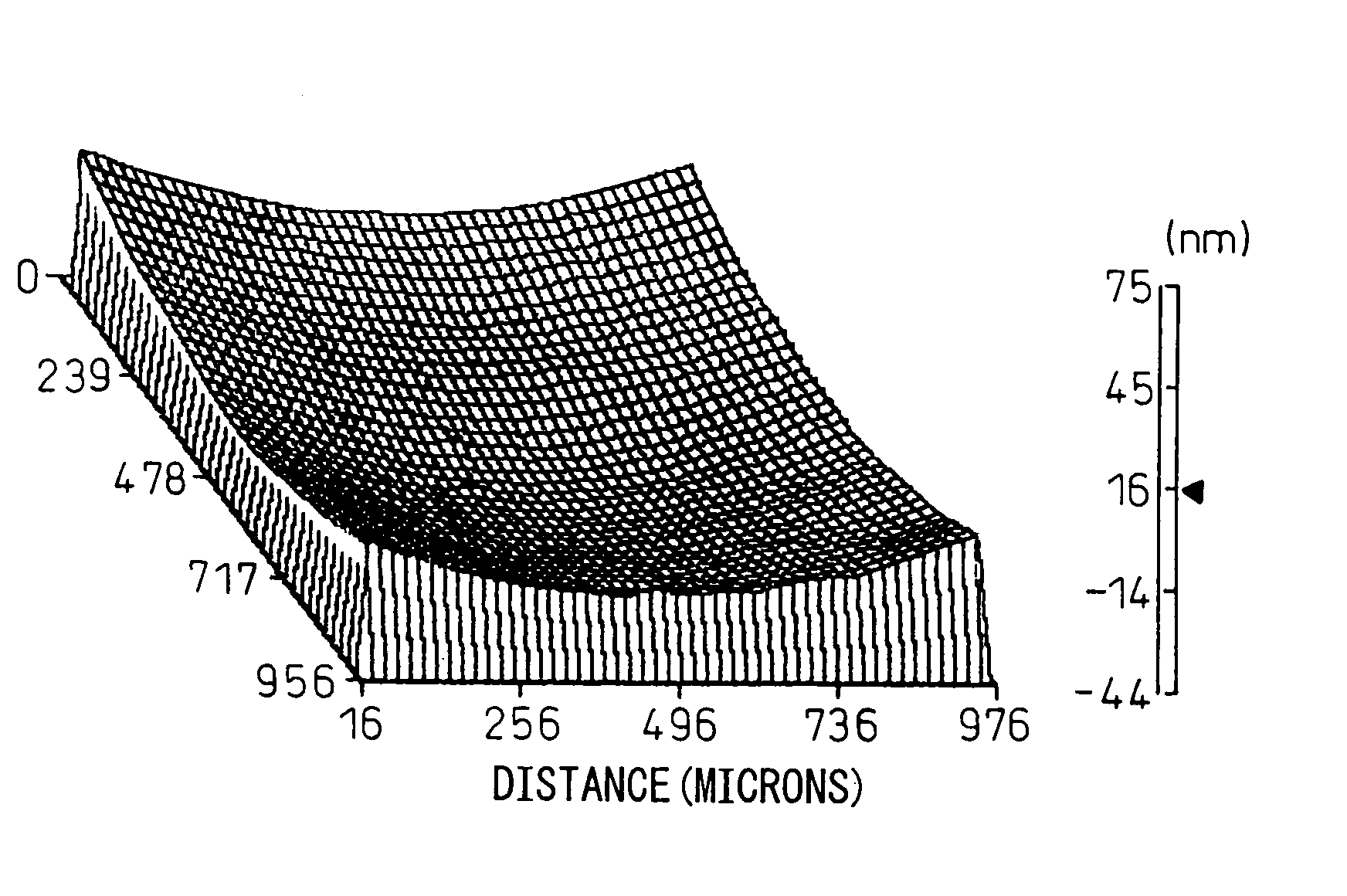
[0030] Eight parts of natural crystalline graphite powder (with an average particle size of 1 μm, manufactured by Nippon Graphite) were added to 92 parts of furan resin (HITAFURAN VF-302 manufactured by Hitachi Chemical), and were thoroughly dispersed and mixed therein to prepare a liquid material for a substrate. Next, the liquid material was charged into a doctor blade type coating machine, and a green sheet was formed by setting the material after coating. The green sheet was then formed into the desired substrate shape, and the thus formed sheet was heated and cured in a drying furnace to obtain a cured plate. The cured plate was 1.5 mm in thickness and rectangular in shape measuring 94 mm×32 mm. The cured plate was then carbonized in a nitrogen gas atmosphere by raising the temperature up to 1000° C. in 50 hours, after which the plate was treated at 1400° C. in a high-temperature vacuum furnace, to obtain a total carbonaceous substrate composed of glassy carbon and graphite in ...
example 2
[0031] Twenty five parts of natural crystalline graphite powder (with an average particle size of 3 μm, manufactured by Nippon Graphite) were added to 75 parts of furan resin (HITAFURAN VF-302 manufactured by Hitachi Chemical), and were thoroughly dispersed and mixed therein to prepare a liquid material for a substrate; after that, a cured plate was obtained by following the same processing steps as those employed in the first example. The cured plate was 1.45 mm in thickness and rectangular in shape measuring 90 mm×30 mm. The cured plate was then carbonized in a nitrogen gas atmosphere by raising the temperature up to 1000° C. in 50 hours, after which the plate was treated at 1400° C. in a high-temperature vacuum furnace, to obtain a total carbonaceous substrate composed of glassy carbon and graphite in proportions of about 50:50 in terms of weight ratio and having a thickness of 1.2 mm, a rectangular shape of 75 mm×25 mm, and a Shore hardness of 80. The thus obtained substrate was...
PUM
| Property | Measurement | Unit |
|---|---|---|
| Temperature | aaaaa | aaaaa |
| Temperature | aaaaa | aaaaa |
| Percent by mass | aaaaa | aaaaa |
Abstract
Description
Claims
Application Information
 - R&D Engineer
- R&D Manager
- IP Professional
- Industry Leading Data Capabilities
- Powerful AI technology
- Patent DNA Extraction
Browse by: Latest US Patents, China's latest patents, Technical Efficacy Thesaurus, Application Domain, Technology Topic, Popular Technical Reports.
© 2024 PatSnap. All rights reserved.Legal|Privacy policy|Modern Slavery Act Transparency Statement|Sitemap|About US| Contact US: help@patsnap.com