Electrostatic chuck and substrate fixing method using the same
- Summary
- Abstract
- Description
- Claims
- Application Information
AI Technical Summary
Benefits of technology
Problems solved by technology
Method used
Image
Examples
first embodiment
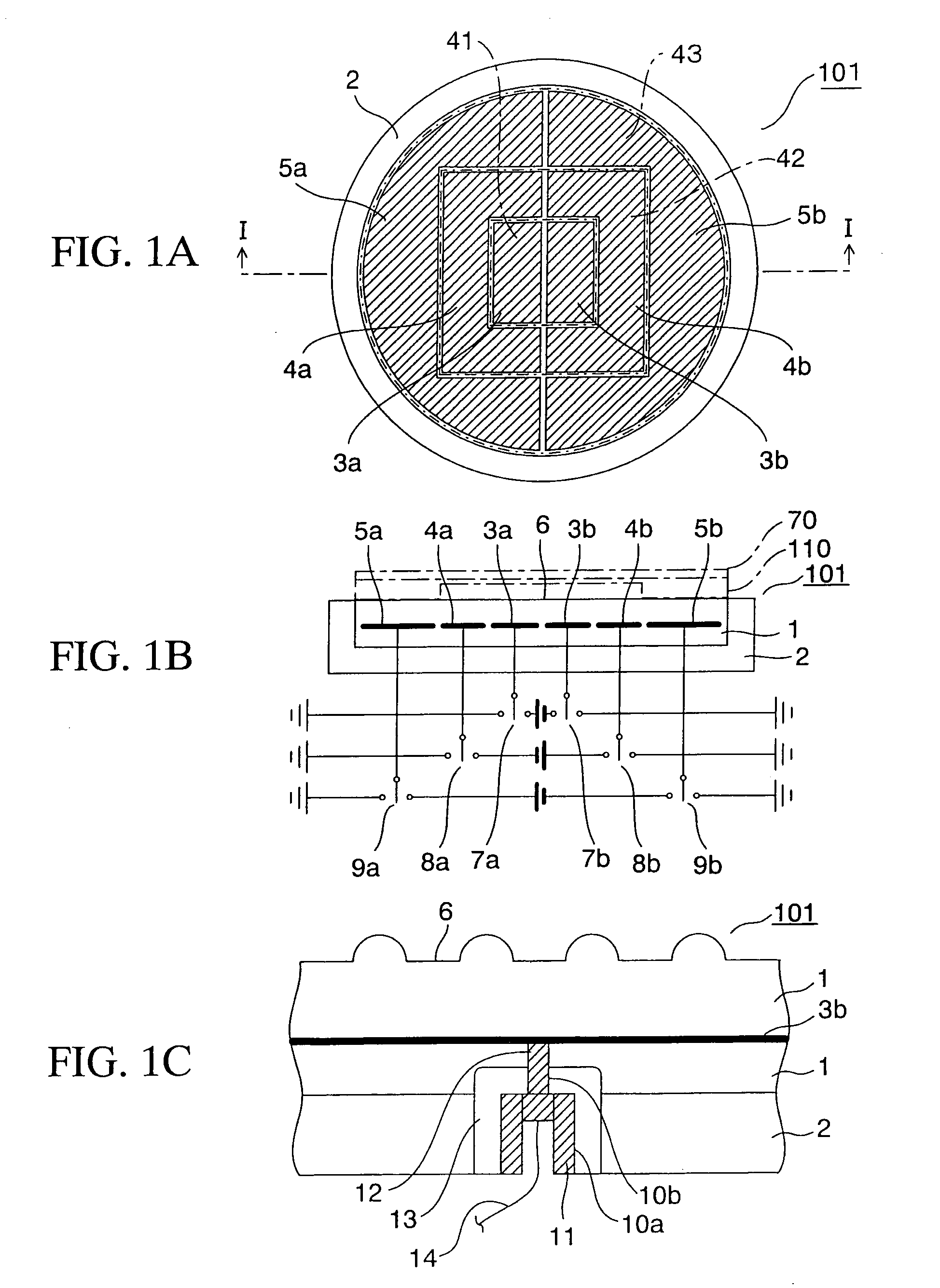
[0029]FIG. 1A is a plan view of an electrostatic chuck according to a first embodiment of the present invention. FIG. 1A shows an arrangement of, in particular, three pairs of electrodes. FIG. 1B is a cross-sectional view taken along the I-I line in FIG. 1A. FIG. 1B also shows how direct current power supplies are connected to the plurality of pairs of electrodes. FIG. 1C is a partial, enlarged, cross-sectional view showing a structure of a part where a wire is drawn out from each electrode of the electrostatic chuck to the outside of the electrostatic chuck. Incidentally, in FIG. 1A, there are omissions for an illustration of an alumina member on the electrodes and an illustration of a substrate.
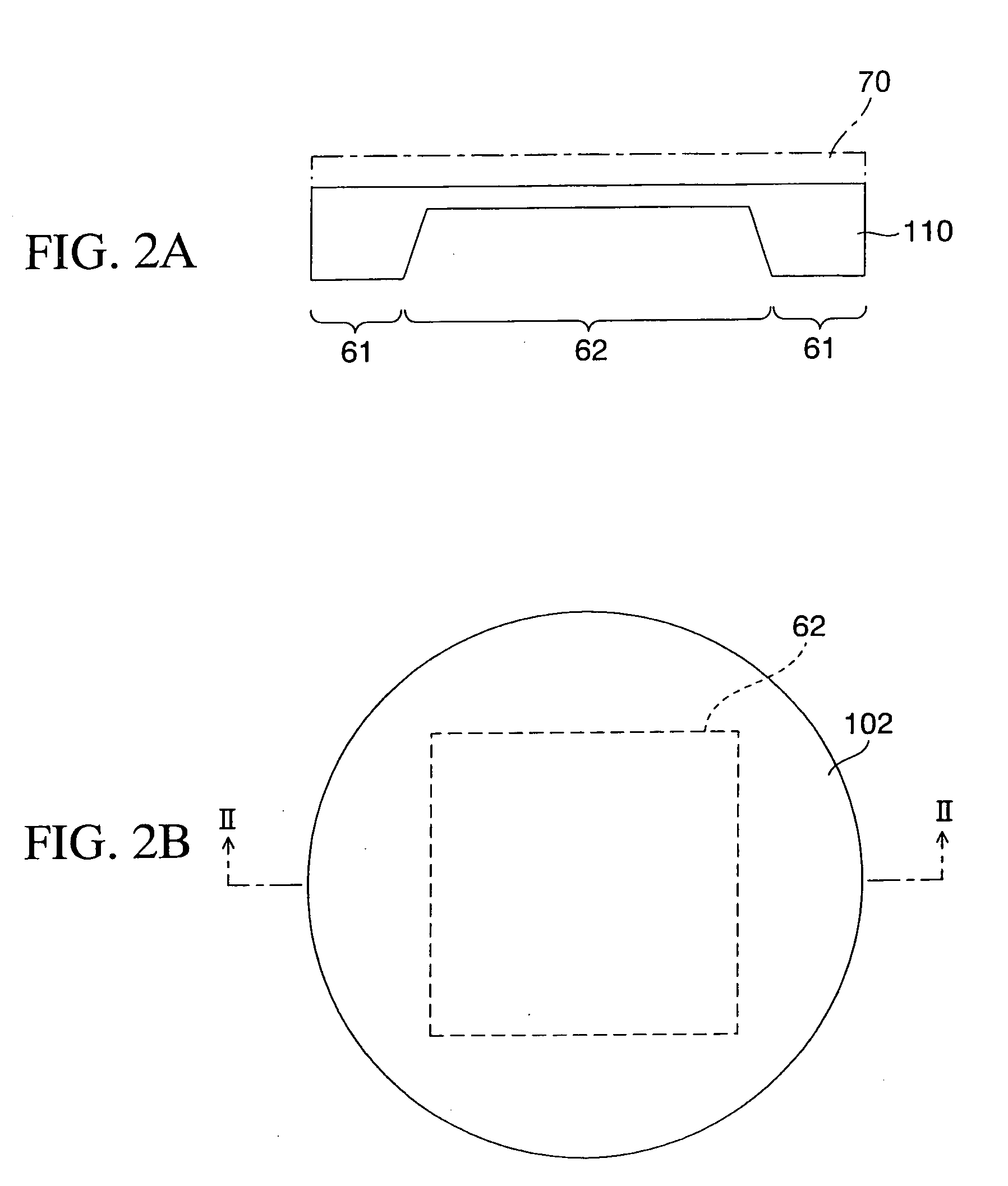
[0030]FIGS. 2A and 2B are respectively diagrams showing a membrane mask substrate which is placed, and held, on the electrostatic chuck. FIGS. 2A and 2B are respectively a cross-sectional view, and a top view, showing the membrane mask substrate. FIG. 2A is a cross-sectional view taken alo...
second embodiment
[0062] Next, descriptions will be provided for a second embodiment of the present invention with reference to FIGS. 5A and 5B.
[0063]FIG. 5A is a plan view of an electrostatic chuck according to the second embodiment of the present invention. FIG. 5A shows an arrangement of, in particular, 4 pairs of electrodes. FIG. 5B is a cross-sectional view taken along the III-III line in FIG. 5A. FIG. 5B also shows how direct current power supplies are connected respectively to the four pairs of electrodes. Incidentally, FIG. 5A omits an illustration of alumina members on the respective electrodes and an illustration of the substrate.
[0064] What makes the second embodiment different from the first embodiment is that the electrodes of the electrostatic chuck 102 are configured of a pair of (a first electrode group constituted of) electrodes 23a / 23b which are arranged in a plane area in the center portion (center region) 44 inside the main body 21, and three pairs of (a second electrode group c...
third embodiment
[0076] Next, descriptions will be provided for an electrostatic chuck according to a third embodiment of the present invention with reference to FIGS. 6 and 7.
[0077] First of all, descriptions will be provided for an electrostatic chuck according to a first example of the third embodiment with reference to FIG. 6A. FIG. 6A is a top view of the electrostatic chuck.
[0078] What makes the electrostatic chuck 103 according to the first example of the third embodiment different from the electrostatic chuck 101 shown in FIG. 1A according to the first embodiment is that, as shown in FIG. 6A, the center region 48 has two pairs of electrodes 81a / 81b and 81c / 81d, one annular belt-shaped region 49 has two pairs of electrodes 82a / 82b and 82c / 82d, and the other annular belt-shaped region 50 has two pairs of electrodes 83a / 83b and 83c / 83d. In other words, each of the three regions has four electrodes. In this manner, the electrostatic chuck 103 has more electrodes than the electrostatic chuck 10...
PUM
 Abstract
Description
Claims
Application Information
 - R&D
- Intellectual Property
- Life Sciences
- Materials
- Tech Scout
- Unparalleled Data Quality
- Higher Quality Content
- 60% Fewer Hallucinations
Browse by: Latest US Patents, China's latest patents, Technical Efficacy Thesaurus, Application Domain, Technology Topic, Popular Technical Reports.
© 2025 PatSnap. All rights reserved.Legal|Privacy policy|Modern Slavery Act Transparency Statement|Sitemap|About US| Contact US: help@patsnap.com


