
Ball valve and method for production thereof

a technology of ball valve and ball valve body, which is applied in the field of ball valve, can solve the problems of high production cost, high material cost, and high process cost of ball valve, and achieve the effects of reducing production cost, simple construction, and increasing accuracy

Inactive Publication Date: 2005-09-22
KITZ CORP
View PDF10 Cites 4 Cited by
  • Summary
  • Abstract
  • Description
  • Claims
  • Application Information

AI Technical Summary

Benefits of technology

The present invention provides a ball valve with a unique construction that allows for decreased weight, lower production costs, and increased reliability. The valve has a body made from a pipe, with stem-inserting holes and a seat-producing part in the middle. Paired inserting members are forced into the body and support the ball rotatably. The valve also has a one-piece construction, with joined portions and component parts in very small numbers. The technical effects of this invention include a lighter weight, decreased production time, and increased reliability of the ball valve.

Problems solved by technology

These ball valves, however, are expensive because they entail high material costs on account of large numbers of man-hours, high prices of blanks, and large numbers of component parts, and require high process costs for the cutting and the assemblage.
Further, since the blanks for processed parts necessitate margins for machining in advance, the costs of materials inevitably increase proportionately.
The ball valve, therefore, encounters the problem of adding a step of tentative assemblage and a step of dissolving the tentative assemblage, increasing the total number of steps of operation and boosting the cost of production.
Even if the tentative assemblage of internal components should be avoided, manufacturing ball valves uniformly with high accuracy as finished products by the technique under discussion has proved extremely difficult.
When the ball valve utilizing a pipe is joined to a pipe by the screw connection, since the construction of this ball valve requires a screw part different from the valve seat member to be welded to the terminal part of the body made of the pipe or fastened to the terminal part (expanded diametrically in advance) of the body made of the pipe, this screw connection incurs the problem of complicating the process of production of the ball valve and unduly elongating the interface dimensions of the valve.

Method used


Image

  • Ball valve and method for production thereof
  • Ball valve and method for production thereof
  • Ball valve and method for production thereof

Examples


Embodiment Construction

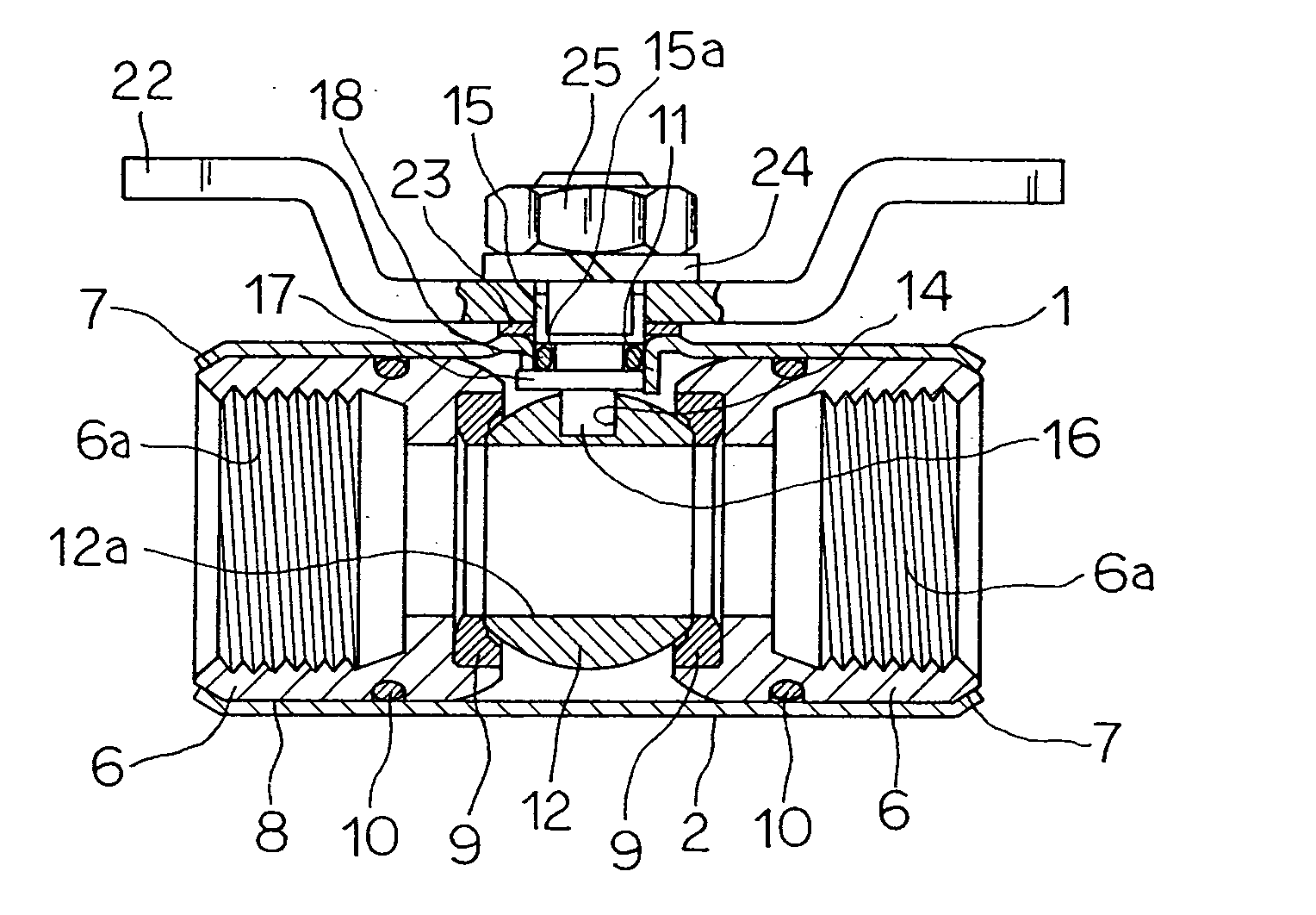
[0060] This invention will be described more specifically below with reference to the accompanying drawings. For purposes of this description, the term “inner” means closer to the center of the valve with respect to a central axis of the valve body (i.e., the axis along which flow occurs), while “outer” means farther from the center of the valve.

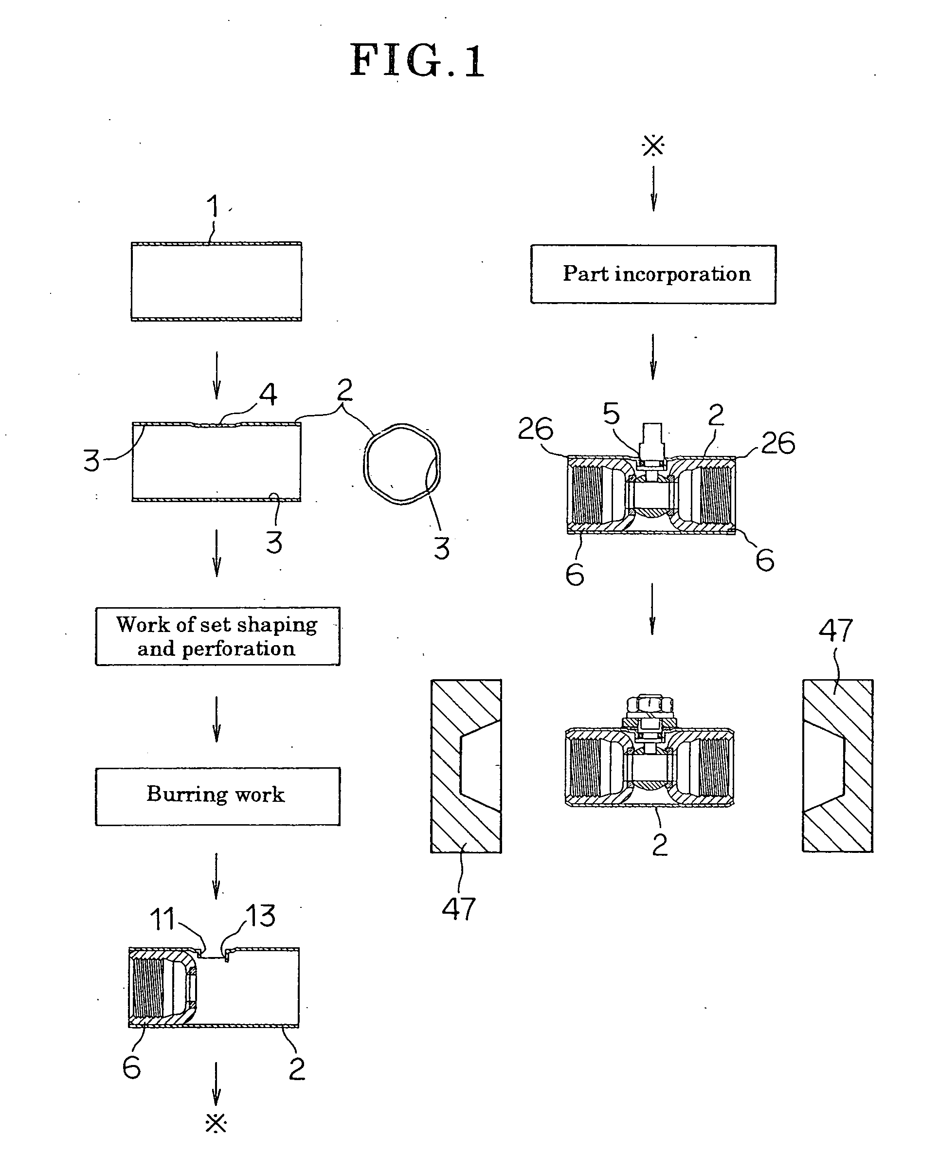
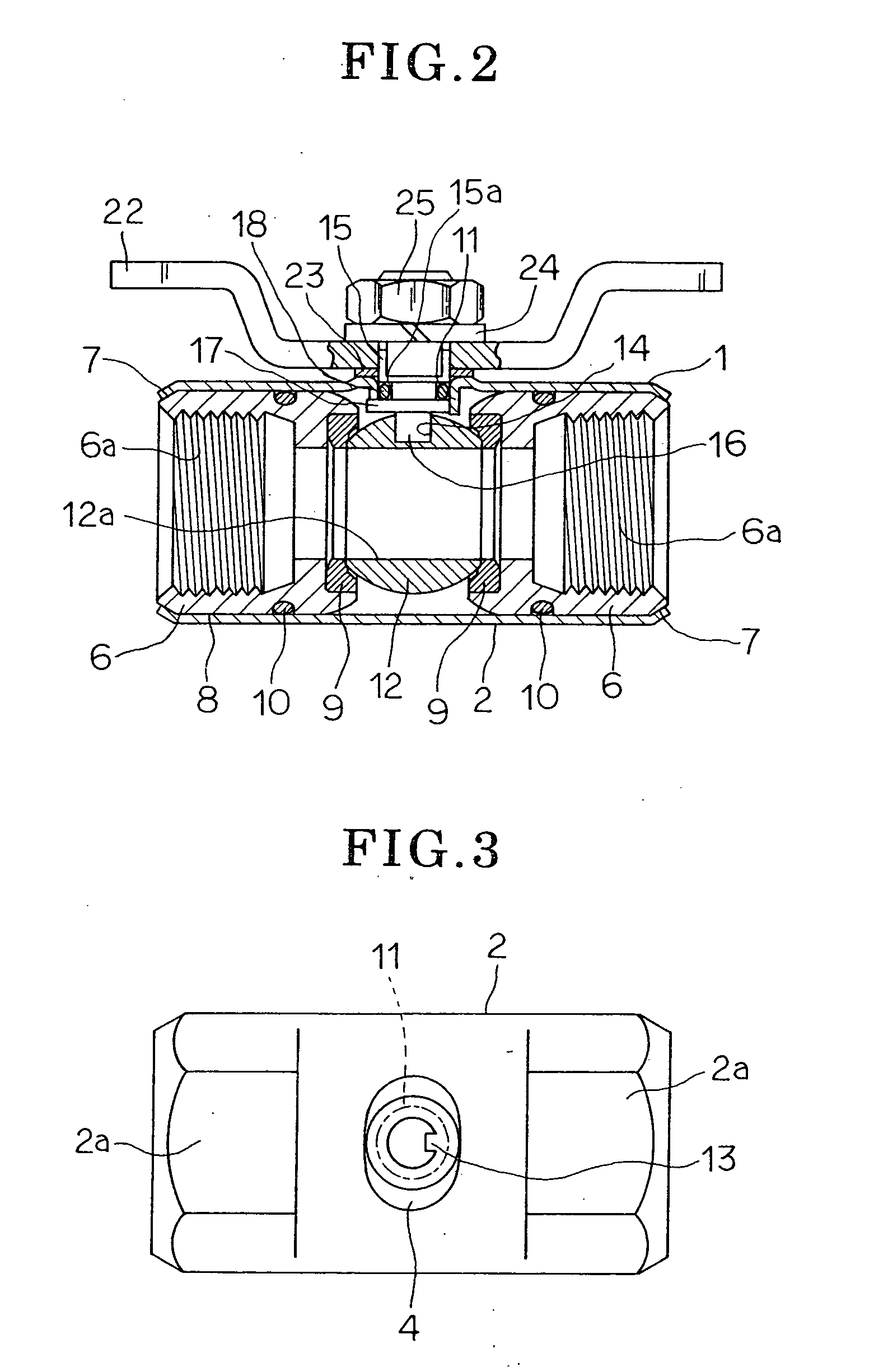
[0061]FIGS. 1 through 10 are intended to illustrate a method for the production of a ball valve as contemplated by the first aspect of this invention.

[0062] In the diagrams, reference numeral 1 denotes a pipe. This pipe 1 is a thin-wall (non-thick-wall) type seamless pipe of copper alloy or stainless steel. Otherwise, it may be a seamed pipe 1 produced by shaping a steel plate in the form of a roll and then converting the roll into a cylinder by joining the opposed edges of the roll as by welding. A body 2 of a ball valve is formed by cutting a predetermined length of this pipe 1, namely the length of a prospective valve box of a ball valv...


PUM

PropertyMeasurementUnit
angleaaaaaaaaaa
lengthaaaaaaaaaa
rotationaaaaaaaaaa

Abstract

The invention provides a ball valve excelling in economy due to the efforts devoted to the reduction of cost, enjoying light weight and high reliability, manifesting high and uniform accuracy, and enabling manufacture of compact finished products having a small interface dimension, and provides a method for the production of the ball valve. The ball valve includes a body formed from a pipe having a predetermined length by subjecting opposite terminal parts (ends) of the pipe to a plastic processing including flaring and diametrical contraction. The body has at a central position a seat-shaping part (seat) formed with a stem-inserting hole, a stem inserted into the stem-inserting hole, a ball disposed non-rotatably at a lower terminal of the stem, and a pair of inserting members having an annular shape forced into the body from opposite terminals of the body. Opposite terminal faces of the body are compression-formed so that the pair of inserting members receive and support the ball rotatably.

Description

[0001] This application is a divisional of U.S. application Ser. No. 10 / 182,552, filed Jul. 30, 2002, which is a national stage application of International application No. PCT / JP01 / 00763, filed Feb. 2, 2001, now allowed.TECHNICAL FIELD [0002] This invention relates to a ball valve that is fitted in a pipe for cold or hot water, air or gas, and used therein to start, stop or control the flow of the relevant fluid, and to a method for the production thereof. BACKGROUND ART [0003] Generally, a forged or cast blank or a round bar material is cut to form a main body, and necessary internal parts are incorporated, screwed or bolted in the main body, thereby assembling ball valves of this class. [0004] These ball valves, however, are expensive because they entail high material costs on account of large numbers of man-hours, high prices of blanks, and large numbers of component parts, and require high process costs for the cutting and the assemblage. They have comparatively great weights a...

Claims


Application Information

Patent Timeline
Patent Type & Authority Applications(United States)
IPC IPC(8): F16K27/06
CPCY10T29/49423F16K27/067Y10T137/0508
Inventor KITAZAWA, SHIGEOGOMI, CHIKASHI
Owner KITZ CORP
Learn More