The control of the flow of the powder through the holes of a
shaker, however, is not accurate, and the resulting coverage of the desired
target surface area is not usually uniform.
This is because in use the agglomerated powder in the container is broken up non-uniformly by the abrupt stoppages of the movement of the container at the extremes of the up and down limits of the applied shaking motion, and also because the flow of the non-uniformly broken up powdered material through the holes cannot be accurately controlled.
Still more complex powder delivery devices also are known including, for example, structures designed for the sequential delivery of measured unit doses of powdered materials from the device.
However, despite their high cost and the often disadvantageous (or damaging) force of their output sprays, homogeneous spray delivery devices such as closed
aerosol cans containing a supply of powdered material and a gas under pressure for discharging a concentrated aerosolized powder
stream, are often used for medicinal powdered material delivery.
Hence, without its interaction with the patient's mouth, an “
inhaler” type device does not provide an easily manipulated device that is suitable for use in the controlled and accurate delivery of aerosolized powders to target surfaces generally, and particularly is not suited to the delivery of powdered materials for reliable target
surface coating into small area surgical sites that are often not readily visible (for example, laparoscopic surgical sites).
However, in those cases in which the surface to be coated is not visible or otherwise readily accessible, the simple “puffer” and similar powdered material delivery device designs have been found not to be efficiently or satisfactorily workable.
Devices / systems of this type, while sometimes useful for the spraying of topical powdered materials in generally open settings, have proven to be unsatisfactory when the target surfaces are located in confined volumes in which a so-called “soft cloud” spray is desired and / or necessary.
This is because factors such as (i) air leakage at the can / valve interface and / or point of attachment of the valve to the spray directing extension member, (ii) the inability satisfactorily to control the velocity of high-pressure aerosolized powder sprays generated by typical
aerosol can valves, and (iii) the well known inability of typical
aerosol cans to reliably
discharge homogeneous sprays when spatially oriented in inverted positions with their release valves disposed below the horizontal, among other factors, all significantly tend to reduce both the reliability and the medical functionality of the conventional aerosol can form of powder
sprayer.
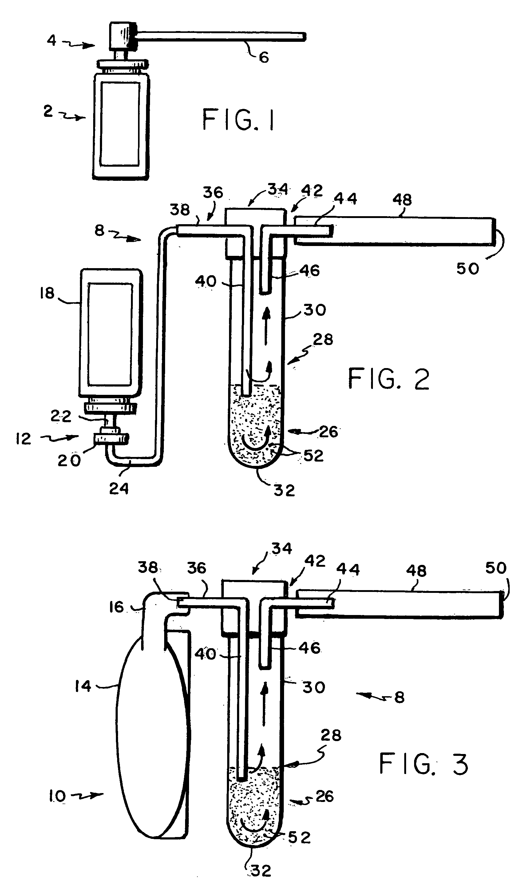
As will appear more fully below, however, both of these propellant sources are cumbersome, expensive and at least somewhat complex.
Further, the systems of which those propellant sources form a part are further limited by the required substantially vertical spatial disposition of their Wolf-type powder reservoir in a manner that renders single-hand-held operation of the device substantially impractical, if not impossible.
In devices / systems such as that depicted in FIG. 3, this often results in the unsatisfactory operation of the remainder of the device.
Thus, the reservoir may be filled, refilled and / or replaced only by the cumbersome and inconvenient disassembly of the cover and the removal of the reservoir therefrom.
In addition, these complexities in the construction of the cover also create a potential for gas leakage at the connection of the lower and top portions of the cover member.
Further, they introduce serious problems in the accomplishment of the satisfactory sterilization the components of the device and its content prior to their use in and / or near open surgical fields.
Accordingly, it will be understood that the tentative operation of the
hand pump mentioned above often is insufficient to generate a gas pulse of adequate duration and pressure to cause the operation of the device just discussed to occur, or if that operation does occur, to cause it to occur in a satisfactory manner.
Similarly, while less likely, the partial release of a pressurized gas pulse in the structure depicted in FIG. 2 due to the tentative actuation of the release valve also can cause insufficient
aerosolization and
discharge of powdered material.
These results can be very problematic because, as mentioned briefly above, there is a natural tendency for individuals performing close, delicate and complex tasks to do so utilizing small movements so as to maintain better control over the effects of their actions.
Consequently, it will be understood that the preferred manner of operating the currently preferred devices is counterintuitive to this natural tendency of operators such as those in the surgical field with results that are at best less than optimum quantities of powdered material spray impinging upon the target surface area.
Furthermore, also as briefly mentioned above, the currently preferred powdered material delivery systems depicted in FIGS. 2 and 3 are cumbersome, expensive and essentially impossible to operate with one hand regardless of whether a pump 10 or a metered propellant source 12 is used.
This results in the surface of the stored powdered material approaching the outlet of the aerosolizing pulses into the reservoir thereby reducing the mixing action of input propellant pulses within the agglomerated powder stored in the reservoir (and indeed, possibly clogging the opening of the output conduit located within the reservoir).
Therefore, tilting of the reservoir reduces the control of the powder
dose aerosolized by each pulse because less powder is influenced by the full
impact of the propellant pulse thereby placing significant constraints upon the manner in which the
system is required to be used.
In addition, since the cross-section of the output conduit is limited, the quantity of aerosolized powder that can be delivered by each propellant pulse also is limited.
Still further, it has been found to be difficult to ensure that all of the powder stored in the reservoir can be delivered satisfactorily by the devices generally depicted in FIGS. 2 and 3.
This adversely affects the efficiency of powdered material use.
Consequently, inefficient overfilling, refilling and / or a switch to a
new device prior to the use of all of the stored powder in a particular reservoir all have been found to be necessary operational drawbacks encountered in the use of the currently preferred
system for the delivery of medicinal powders to and in the vicinity of surgical sites.
In summary, therefore, the currently preferred concept for the generation and spray of powdered materials is cumbersome in structure and typically requires two-handed operation by the user thereby preventing the user from performing other tasks with one of his hands.
Also, the various components of the device are not easily sterilized, yet they are designed for reuse rather than being single-use disposable devices.
These are important disadvantages, particularly in a surgical setting in which the available space for each surgeon or
technician to perform is limited yet the efficiency with which all surgical tasks can be performed within the available area is significant.


