
Assembly, system and method for acoustic transducers

a technology of acoustic transducers and components, applied in the field of recording and reproducing spatial sound, can solve the problems of harmful time differences, high cost of ambisonics techniques, and the practicability of reproducing sound according to the original recording situation, and achieves the effect of good dynamics and easy manufactur

Active Publication Date: 2012-12-25
MARTIN KANTOLA CONSULTING
View PDF14 Cites 25 Cited by
  • Summary
  • Abstract
  • Description
  • Claims
  • Application Information

AI Technical Summary

Benefits of technology

[0018]Furthermore, in accordance with an aspect of the present invention, an assembly of acoustic transducers is provided, enabling the reproduction of signals of different directions in the XY plane with two or alternatively three acoustic transducers, such as loudspeakers. In accordance with another aspect, the assembly of acoustic transducers also enables the reproduction of the signals in the XYZ plane. In this case, in accordance with an aspect, signals of the elevation plane (Z plane) can be reproduced with two different elements.
[0026]Still another additional aspect of the invention is to provide a supplementary device associated with the signal of the arrangement and the method according to the invention for narrowing the directional patterns of a received signal to improve resolving power.
[0028]The audio signal-processing unit comprises a separation / combination part, which may comprise combination and / or separation means. The units of an acoustic transducer, such as microphone capsules, are placed in the immediate vicinity of each other, and thus sound arrives at all capsules as simultaneously as possible. Such placement of microphones, a so-called one-point arrangement, enables transfer of accurate direction information. Utilization of such one-point technique enables signals to be subjected to summing and subtraction.
[0029]Still another object of the invention is to provide a microphone in a conference room, for example, as such a microphone utilizes the method of the invention and the equipment implementing the method in such a manner that the signals of the different directions are separated in accordance with the method. Signals received from different directions can be separated, compared and attenuated, if need be, allowing a conference microphone to separate / emphasize the sound source / speaker of one direction at a time, and thus the receiving party to the negotiation finds it easier to identify speech and the speaker.
[0032]The placement of microphones according to an aspect of the invention enables the provision of a microphone for instance in a conference room, whereby the microphone utilizes the method of the invention and the equipment implementing the method such that signals of different directions are separated in accordance with the invention. In this case, signals received from different directions can be separated, compared and attenuated, if need be, allowing a conference microphone to separate / emphasize the sound source / speaker of one direction at a time, and thus the party receiving the conference finds it easier to identify speech and the speaker. The microphones may be dual-diaphragm microphone capsules, known per se, whose small capsular structure allows the arrangement to be made compact. A new kind of capsule arrangement enables similar reproduction from all directions. The reproduction of the microphones may be corrected electrically or acoustically. The coupling arrangement of the invention enables the simultaneous use of dual-diaphragm microphone elements as a figure of eight containing a directional pattern having two directional pattern halves and circular, this enabling determination of the exact position of the sound source according to the invention.
[0035]Accordingly, the assembly of acoustic transducers accomplishes a compact microphone. As few as two small figure-of-eight capsules achieve an 8.1 surround microphone, for example. The new assembly of acoustic transducers is advantageous and easy to manufacture, since the structure of one capsule is known. The utilization of the structure in a new manner enables an acoustically well operating surround microphone, since the time and transfer function differences of the capsules are minimal. A 2D or 3D Surround microphone has good dynamics, since the diaphragms of the capsules may be sufficiently large without compromising said advantage. For its operation, the new kind of arrangement does not require frequency, phase or other electrical compensations and thus sound quality remains as authentic as possible.

Problems solved by technology

However, such 5.1 equipment requires six channels and does not include elevation information.
However, it is practically impossible to reproduce sound according to the original recording situation, and consequently, techniques have to be employed for producing a sound world that sounds as authentic as possible.
However, in recording sound, the Ambisonics technique is expensive.
This distance causes harmful time differences.

Method used


Image

  • Assembly, system and method for acoustic transducers
  • Assembly, system and method for acoustic transducers
  • Assembly, system and method for acoustic transducers

Examples


Embodiment Construction

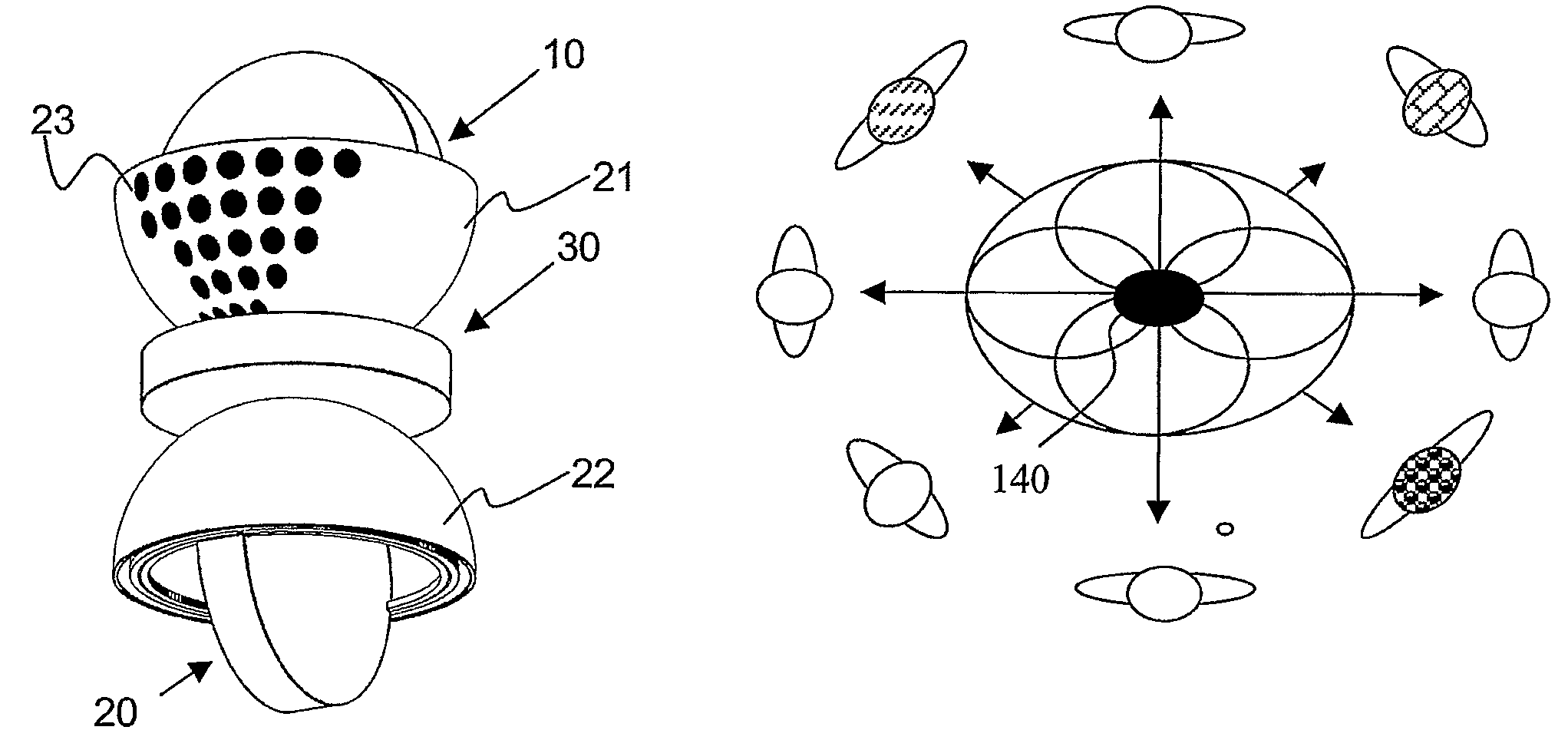
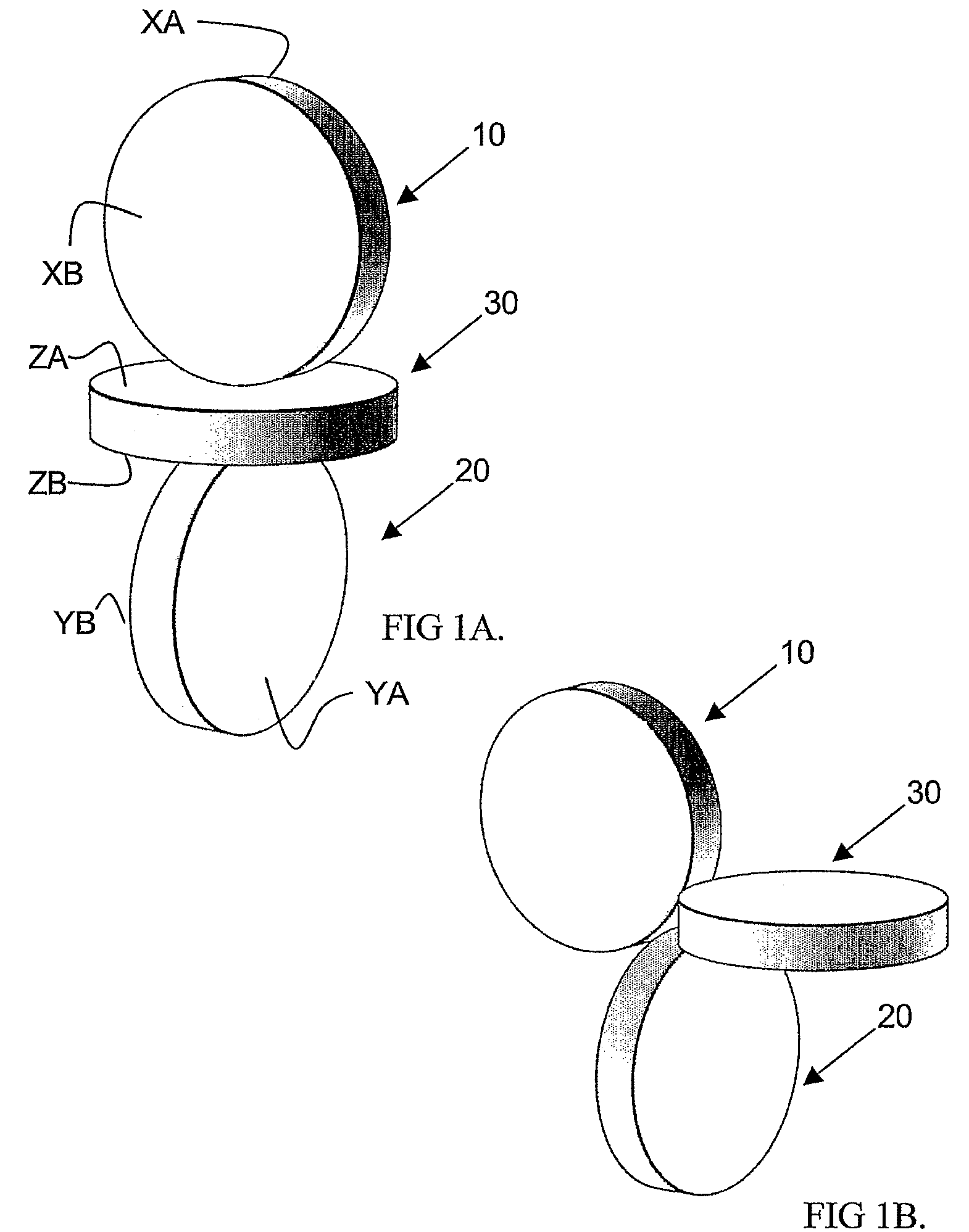
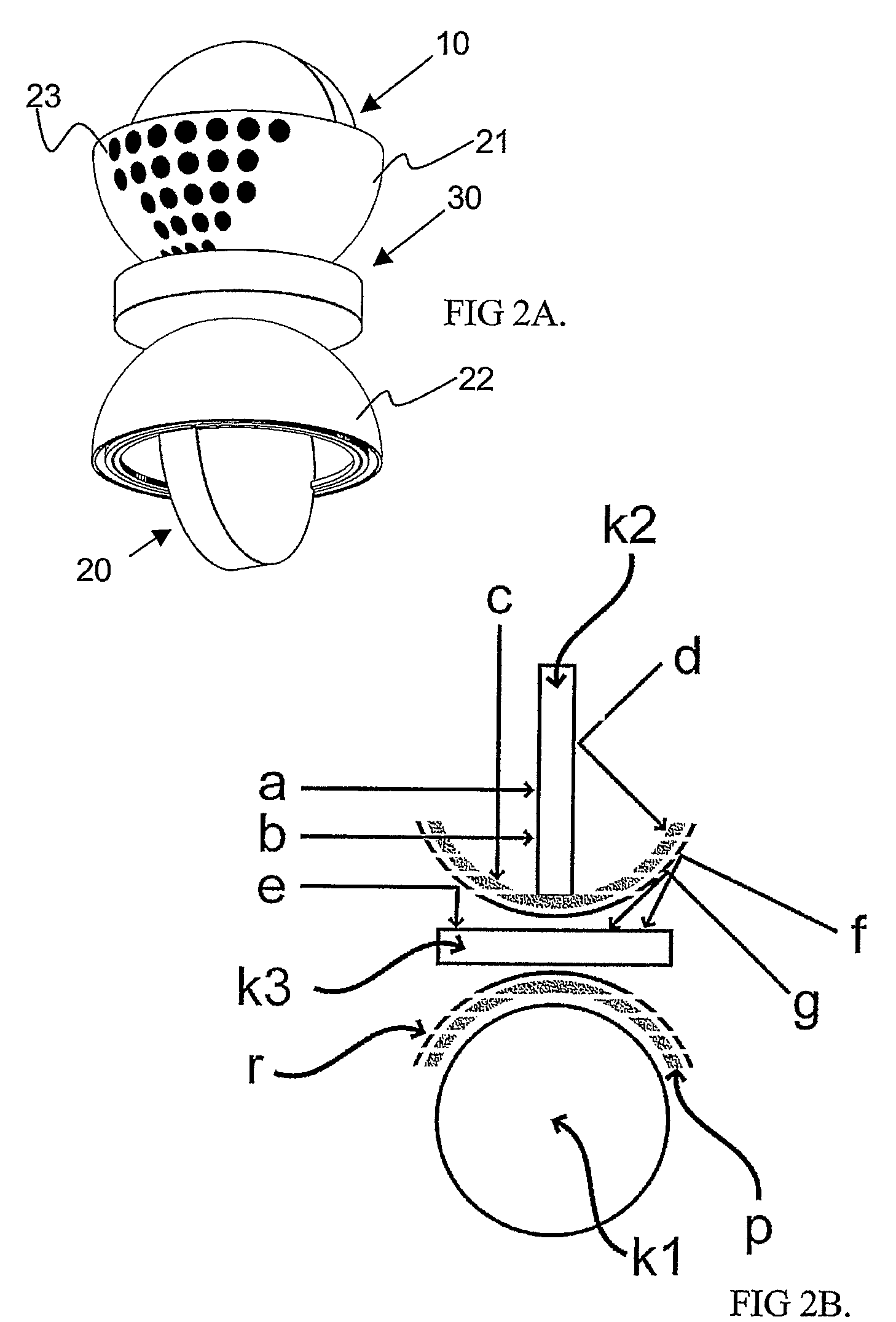
[0059]FIG. 1A shows an embodiment of the structure and placement of an assembly of acoustic transducers. The assembly comprises three superimposed acoustic transducers 10, 20, 30 for receiving and reproducing acoustic signals, the first acoustic transducer 10 having a figure-of-eight directional pattern in the horizontal forward / backward direction (herein, in the direction of the X coordinate axis) and including directional pattern halves XA, XB. The second acoustic transducer 20 has a figure-of-eight directional pattern in the horizontal direction right-left (in the direction of the Y coordinate axis), including directional pattern halves YA, YB. The third acoustic transducer 30 has an upward / downward directional pattern in the direction of the Z coordinate axis, having a circular form when observed in the XY plane and including directional pattern halves (ZA, ZB). In the assembly, the centre points are as close to each other as possible and yet they cover as little of each other a...


PUM


Abstract

The invention relates to an assembly of acoustic transducers, a system and a method for receiving and reproducing sound. The assembly comprises a first acoustic transducer having a directional pattern of the shape of a figure of eight in the direction of an X axis of a XYZ coordinate system, and a second acoustic transducer placed perpendicularly relative to a first capsule and providing a directional pattern of the shape of a figure of eight in the direction of a Y axis of a XYZ coordinate system. The assembly is characterized in that it further comprises a third acoustic transducer placed perpendicularly relative to the first and second acoustic transducers, enabling the implementation of spatial sound both in a XY plane and in a XYZ plane by using these acoustic transducers placed in accordance with an axis of the axes of the XYZ coordinate system. The invention further provides a system and a method for processing signals received with the assembly.

Description

BACKGROUND OF THE INVENTION[0001]The invention relates to the technique of recording and re-producing spatial sound. As home theatres are becoming more common, a large portion of consumers has a home theatre. The aim of home theatres is to reproduce credible spatial sound, such as in a recording situation. At present, the equipment is most generally of type 5.1, including two front loudspeakers, a central loudspeaker, two back loudspeakers and one subwoofer controlled by the LFE channel for low-frequency sound effects. Other such Surround systems include the 7.1, 8.1 and 10.2 systems, for example, part of which are designed only for theatre use, not for an ordinary consumer. However, such 5.1 equipment requires six channels and does not include elevation information. In such systems, the loudspeakers are to be placed at the designed locations around the listener.[0002]However, it is practically impossible to reproduce sound according to the original recording situation, and conseque...

Claims


Application Information

Patent Timeline
Patent Type & Authority Patents(United States)
IPC IPC(8): H04R3/00H04R5/00H04RH04R5/027H04S3/00
CPCH04R3/005H04R5/027H04S2420/11H04R2205/022H04R2420/07H04S3/00
Inventor KANTOLA, MARTIN
Owner MARTIN KANTOLA CONSULTING
Learn More