Electrochemical fabrication methods incorporating dielectric materials and/or using dielectric substrates
a technology of dielectric materials and dielectric substrates, applied in the field of electrochemical fabrication, can solve the problems of destructive separation of masking materials from substrates, and achieve the effect of enhancing electrochemical fabrication
- Summary
- Abstract
- Description
- Claims
- Application Information
AI Technical Summary
Benefits of technology
Problems solved by technology
Method used
Image
Examples
first embodiment
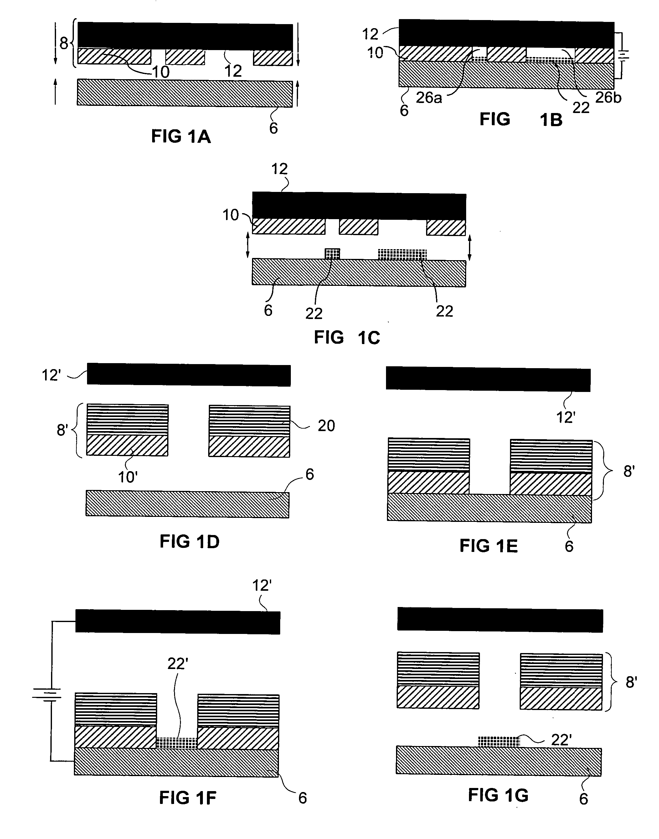
[0086] the invention, based on the process of FIG. 5, deposits a conductive material and another material that is conductive at the time of deposition but is made to become insulative (or dielectric) after deposition (i.e. the deposition involves a precursor to what will be a dielectric material). If the requirements for dielectric material are not stringent (i.e., in terms of dielectric constant), it may be possible to deposit a photoconductive material while the material is being illuminated. After formation of the fabricated device, the device or at least those portions of the device formed from the photoconductive material may be sealed to prevent illumination thus achieving the desired dielectric attributes. One example of such a photoconductor is amorphous silicon. Such a photoconductor may be electrophoretically deposited.
second embodiment
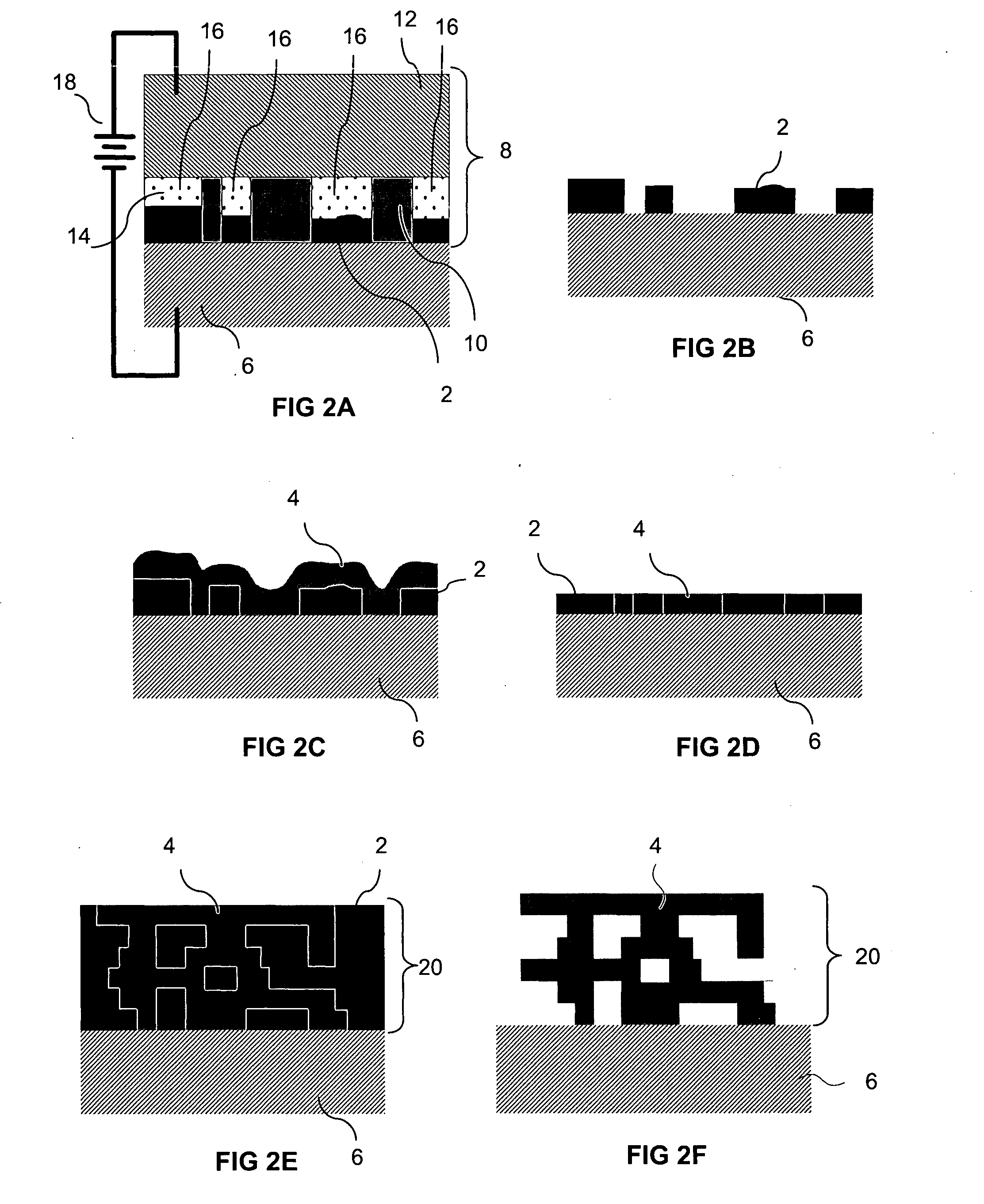
[0087] the invention, based on the process of FIG. 5, deposits a conductive material (e.g. by electroplating) and electrophoretically deposits insulating particles which are coated with a thin conductive film (e.g., a metal), such that the particles and the deposit is initially conductive due to intimate contact between the metal surfaces of each particle. After formation, the conductive paths connecting the surfaces of the particles together are broken to yield an insulative material. For example, the deposit can be heated to cause melting of the conductive surface films. The melted material may then form isolated pockets of conductive material, as a result of surface tension and de-wetting effects. Alternatively, a flow of hot gas or non-conductive, potentially solidifiable, liquid may be used to force out the conductive material and even to replace it with a dielectric material. Alternatively, the structure may be subjected to an etchant that attacks the conductive material of th...
tenth embodiment
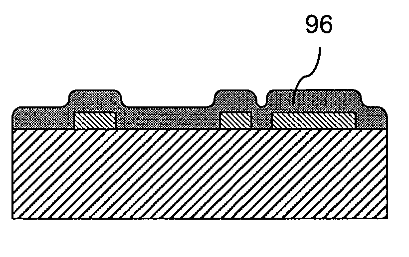
[0148]FIGS. 16A-16D schematically present side views of a sample structure which illustrate selected states of a process for electrochemically fabricating a structure on a dielectric substrate according to the invention. In FIG. 16A, a dielectric 362 is shown as having been metallized with a thin film or seed layer 364, e.g., a layer of Au over Cr, Au over Ti, Au over W, Au over Ti / W. In FIG. 16B, a structure 366 is shown as having been formed and the structure is shown as still being embedded in a sacrificial material 368. In FIG. 16C, the sacrificial material 368 is shown as having been removed (e.g. by etching). In FIG. 16D, the metal film 364 is shown as having been removed in exposed regions. The removal of the film may occur in a one or two step etching process, e.g. one to remove the upper most portion (i.e. initially exposed portion—e.g. Au) and a second etch to remove any adhesion layer material (e.g. Cr, Ti, W, or Ti / W). This etching is preferably performed using a dilute ...
PUM
| Property | Measurement | Unit |
|---|---|---|
| Dielectric polarization enthalpy | aaaaa | aaaaa |
| Electrical conductor | aaaaa | aaaaa |
Abstract
Description
Claims
Application Information
 - R&D
- Intellectual Property
- Life Sciences
- Materials
- Tech Scout
- Unparalleled Data Quality
- Higher Quality Content
- 60% Fewer Hallucinations
Browse by: Latest US Patents, China's latest patents, Technical Efficacy Thesaurus, Application Domain, Technology Topic, Popular Technical Reports.
© 2025 PatSnap. All rights reserved.Legal|Privacy policy|Modern Slavery Act Transparency Statement|Sitemap|About US| Contact US: help@patsnap.com


