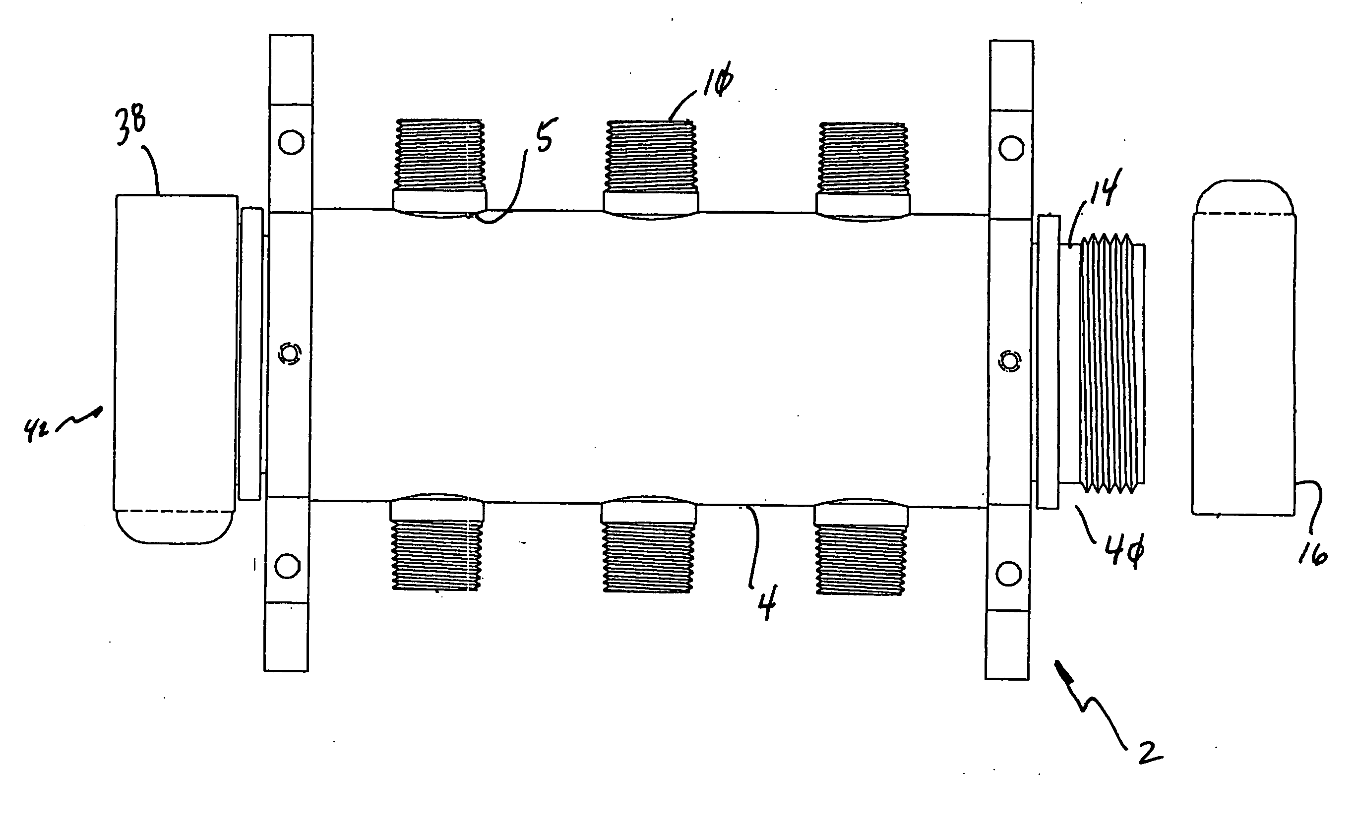
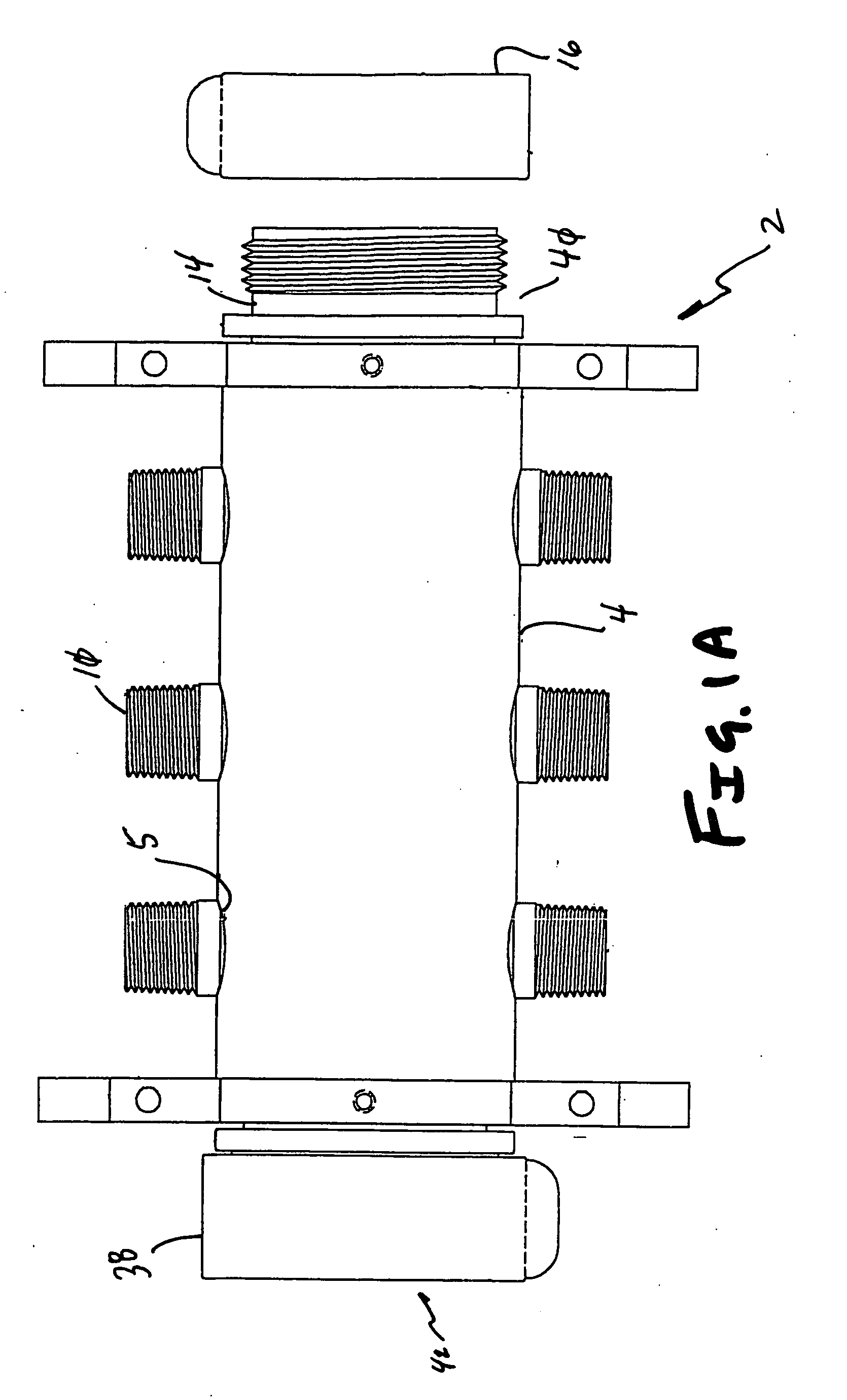
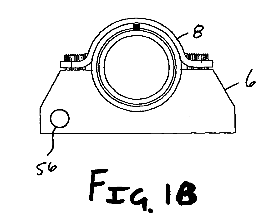
[0008] It is thus one aspect of the present invention to provide a manifold that is adapted to receive at least one fluid source and distribute it through a plurality of outlets. More specifically, one embodiment of the present invention employs an inlet that is adapted to receive various types of fluid interfaces, such as a threaded coupler, a quick connect / disconnect, a snap fit, or a biased-fit mechanism. Hence, a manifold body is provided, such as a cylinder, which is adapted to hold fluid and provide locations for at least one outlet. Preferably, the outlet is in fluid communication with a mechanism that selectively controls the
mass flow of the exiting fluid, such as a valve or
nozzle. Alternatively, or in conjunction with the flow control device, an
interfacing means, such as threads or a quick connect / disconnect mechanism, is incorporated on the outlet to allow for selective
interconnection to a fluid distribution device, such as a hose. The outlet hose interconnections are preferably easy to interconnect, thereby reducing the time required for
system implementation. In addition, as will be appreciated by one skilled in the art, the manifold of the present invention may be scaled to any size. However, it is envisioned that a plurality of outlets are provided that are smaller than the inlet, such that a plurality of pressurized fluid streams emanate from the manifold body.
[0012] It is a further aspect of the present invention to provide a manifold that can be elevated a predetermined distance from a generally planar surface. Preferably, in one embodiment of the present invention, one or more removable brackets or clamps are attached to the manifold, wherein hoses are quickly and easily interconnected thereto without increasing the probability of
hand injury. The brackets are adapted to cradle the manifold body and are interconnected thereto using screws, adhesives, bolts, welds, hinges, buckles, grommets, clamps etc. The bracket may additionally include apertures, or other devices, adapted to provide a location for selective
interconnection with a substantially flat object, such as a
wood plank or concrete slab. Alternatively, the manifold may be used without support devices, on perhaps uneven ground where such features may become a hindrance. In addition, support may not be needed when a plurality of manifolds are directly connected to each other. More specifically, it is envisioned that adapters may be utilized that allow for direct manifold-to-manifold connection without the requirement of a hose therebetween. In this configuration selectively interconnecting support devices may be placed in order to provide the most efficient
structural stability. Finally, the support devices may be adapted to be used to store the manifold when not in use.
[0013] It is yet another aspect of the present invention to provide a manifold that is constructed from a material that is strong and resistant to degradation from
corrosion or foreign objects such as chemical compounds. Ideally, a high modulus material that is capable of limited elastic deformation is employed that withstands high stresses, and thus is capable of transporting fluids under
high pressure. Preferably, one embodiment of the present invention is constructed of an aluminum
alloy, such as AL 6061-T6. However, other
corrosion resistant materials known in the art may be employed, for example stainless steel,
inconel,
brass, plastic,
magnesium, or
titanium. One skilled in the art will appreciate that various manufacturing methods, such as
casting,
machining,
forging,
stamping, or a combination thereof, may be used to form the manifold without departing from the scope of the invention. Moreover, factors such as the environment of use, conveyed fluid, vibrational dynamics, the method of manufacture, cost, etc., will have to be assessed prior to any
material selection. A related aspect of the present invention is that it be easily repaired, wherein damaged components may be patched, re-threaded, welded, brazed or otherwise repaired or replaced.
[0014] It is still yet an aspect of the present invention to provide a manifold that is adapted for use in a variety of fields and situations. More specifically, the present invention may be employed at disaster areas to provide
potable water to the victims, at locations exposed to biological, chemical, or nuclear
contamination to aid in the decontamination of individuals or property, in
agriculture to aid in
irrigation and
pesticide and / or herbicide applications. Alternatively, the apparatus may be used in recreational applications to provide water and other treatments to golf courses and athletic fields, in amusement and water parks, in environmental applications such as oil
clean up, in fire fighting, in hospitals, and in military and civilian fueling operations. The possibilities are limitless where a single fluid
stream is required to be split into many steams, and where two manifolds are interconnected in series or parallel. Alternatively, the flow may be reversed such that many small streams are converted into a large one, such in
waste disposal. One use that is of note, due to the current geopolitical environment, and of great interest to
homeland security and the military, is that of chemical, biological, and nuclear
contamination removal. The present invention is adapted to allow for quick deployment of a plurality of cleaning stations and / or showers, wherein many individuals may be efficiently treated. More specifically, a single fluid source, generally treated with a counter agent, may be distributed via manifolds and hoses to a plurality of decontamination locations, thereby alleviating the need to mix and pump multiple sources of treated fluid.


