
Solar control coated glass composition

a technology of solar control and composition, applied in the direction of coatings, layered products, chemistry apparatus and processes, etc., can solve the problems of not meeting the performance requirements in an economic manner, interference colors (iridescence) which are visible, and objectionable iridescence in most glazing applications, etc., to achieve low haze, improve energy efficiency performance, and thin coating

Inactive Publication Date: 2005-09-08
ARKEMA INC
View PDF19 Cites 16 Cited by
  • Summary
  • Abstract
  • Description
  • Claims
  • Application Information

AI Technical Summary

Benefits of technology

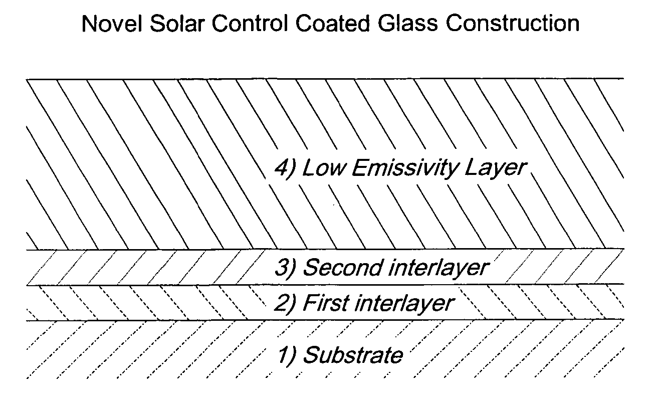
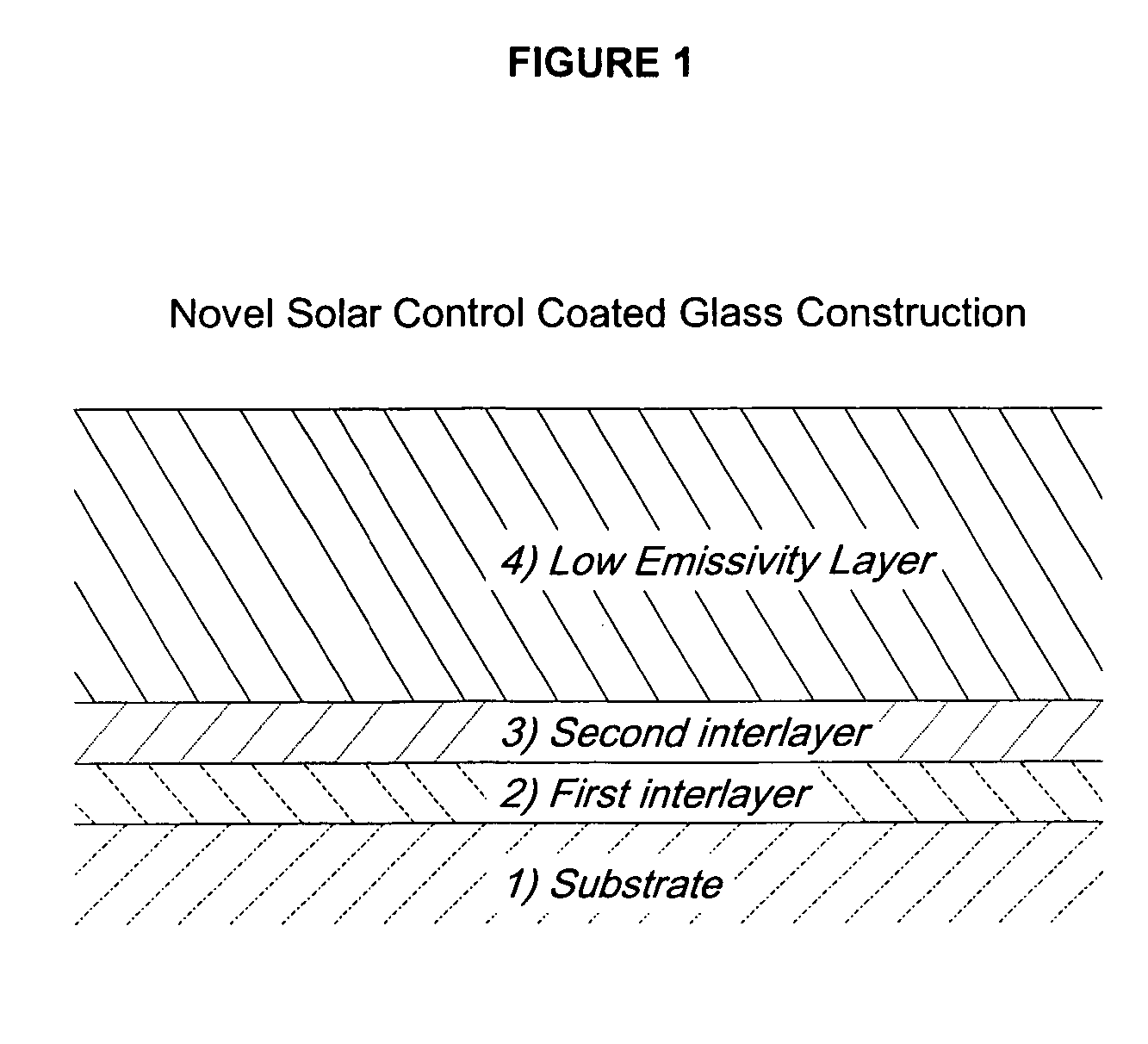
The invention is a coated glass that allows a high level of light transmission and neutral color. It also has low haze and high energy efficiency. The coating includes a transparent substrate, two layers with high and low refractive indices, and a low emissivity layer. The thickness of the layers is about ⅙th of a design wavelength. This combination of layers results in a thin, economical coating that eliminates the need for separate layers for solar absorption and iridescent suppression.

Problems solved by technology

As explained below, various technologies have been employed to meet the requirement for solar-control and low emissivity glass, however, no one system has successfully met all of the performance requirements in an economic manner.
The deposition of thin transparent coatings onto a transparent substrate having a different refractive index than that of the coating generally results in interference colors (iridescence) which are visible in reflectance.
Iridescence is objectionable in most glazing applications.
The constructions taught by McKown, et al. are not readily able to produce coatings which have both neutral reflected color and visible transmittances greater than 70%.
Unfortunately, solar control coatings of the present art produces solar control coatings by stacking heat absorbing and low emissivity layers.
The combined thicknesses of these two layers either leads to coatings having relatively high levels of haze or limited performance, for example a relatively high emissivity.
These thicker coatings are both more difficult to produce because of the additional layer and increased thickness and more expensive to produce.

Method used


Image

  • Solar control coated glass composition
  • Solar control coated glass composition

Examples


Embodiment Construction

[0037] The solar control coated transparent substrate composition of the present invention contains at least three distinct layers, in order from the substrate outward: a first interlayer, a second interlayer, and a low-emissivity layer. The coated substrate composition is produced by depositing the layers sequentially on a heated transparent substrate. Additional optional layers may also be present in the composition.

[0038] Energy efficiency properties applied to windows are typically expressed in terms of total solar energy transmittance (g) and thermal transmittance (U).

[0039] The first interlayer is a solar absorbing layer having a relatively high refractive index. The refractive index is in the range of 1.70 and 2.00, preferably between 1.75 and 1.90, and most preferably between 1.75 and 1.85.

[0040] The solar absorbing layer is composed of SnO2 containing a dopant. The dopant is preferably antimony although the dopant can be any element selected from the group consisting of ...


PUM

PropertyMeasurementUnit
optical thicknessaaaaaaaaaa
refractive indexaaaaaaaaaa
thicknessaaaaaaaaaa

Abstract

A solar-control transparent substrate composition is presented having a transparent substrate; a first solar heat absorbing interlayer having a high refractive index; a second interlayer having a low refractive index; and a low emissivity layer; where the combined optical thickness of the first and second interlayers is about ⅙th of a 550 nm design wavelength. Also provided is a method of producing the improved, coated, solar-controlled transparent substrate. The solar-control transparent substrate composition eliminates the need for a separate solar absorbing layer, resulting in a thinner, more economical construction with reduced haze. It is especially useful with glass substrates.

Description

REFERENCE TO RELATED APPLICATION [0001] This application claims the benefit of U.S. Provisional Application Ser. No. 60 / 549,574, filed Mar. 3, 2004.FIELD OF THE INVENTION [0002] This invention relates to a solar control coated transparent substrate having solar control, low emissivity and non-iridescent properties. The coated article comprises a transparent substrate, a low emissivity metal oxide layer and a layer positioned between the substrate and the low emissivity layer which provides both solar heat absorbing and anti-iridescent functions. The heat absorbing and anti-iridescent layer comprises a first interlayer which has a relatively high refractive index and comprises a solar absorbing material and a second interlayer having a relatively low refractive index positioned adjacent to the low emissivity layer. The combined optical thickness of the first and second interlayers are about ⅙th of a 550 nm design. This construction eliminates the need for a separate solar absorbing l...

Claims


Application Information

Patent Timeline
Patent Type & Authority Applications(United States)
IPC IPC(8): B32B15/00
CPCC03C17/3417C03C2217/734C03C17/3441C03C17/3435
Inventor MCKOWN, CLEM STEFFLER JR.
Owner ARKEMA INC
Learn More