
Polyelectrolyte multilayers that influence cell growth methods of applying them, and articles coated with them

a polyelectrolyte and multilayer technology, applied in the field of polyelectrolyte multilayers that influence cell growth, can solve the problems of poor device performance, increased risk of infection, and detrimental clinical complications, and achieve the effect of preventing cell adhesion and preventing cell adhesion

Inactive Publication Date: 2005-09-01
RUBNER MICHAEL F +2
View PDF4 Cites 49 Cited by
  • Summary
  • Abstract
  • Description
  • Claims
  • Application Information

AI Technical Summary

Benefits of technology

[0008] One aspect of the present invention relates to a method of coating a surface, comprising sequentially depositing on a surface, under pH-controlled conditions, alternating layers of polymers to provide a coated surface, wherein a first polymer is selected from the group consisting of pH dependent cationic polyelectrolytes and neutral polymers, and a second pol

Problems solved by technology

Commonly, proteins and cells uncontrollably attach onto medical implant surfaces, which may ultimately lead to undesirable fibrous encapsulation, detrimental clinical complications, an increased risk of infection, and poor device performance.
Such a foreign body response can lead to clinical complications, hinder device performance, or necessitate implant removal, so by controlling (i.e. usually preventing) the adsorption of proteins to the biomaterial, one can attempt to reduce cell attachment and any negative physiological response.
Despite its general success in preventing undesirable protein and cell adhesion, PEO is limited in its use; due to its high water solubility, PEO must be grafted to surfaces, yet incomplete surface coverage remains a dilemma.
While polymeric or oligomeric ethylene glycol (PEO, PEG, or o-EG) often exemplifies the bioinert background material in such an approach, it unfortunately succumbs to auto-oxidation and hydrolytic degradation over time and thus has poor stability in long-term clinical applications.
However, potential problems with incomplete, non-uniform surface coverage, possible multiple synthetic steps, and the restriction of SAMs to silicon or gold substrates greatly limit these techniques for creating bioinert coatings.
Despite these studies, there still has been no systematic investigation of how cell behavior depends upon the molecular-level processing and structure of multilayers, features that are so inherently easily controlled in the layer-by-layer deposition approach.

Method used

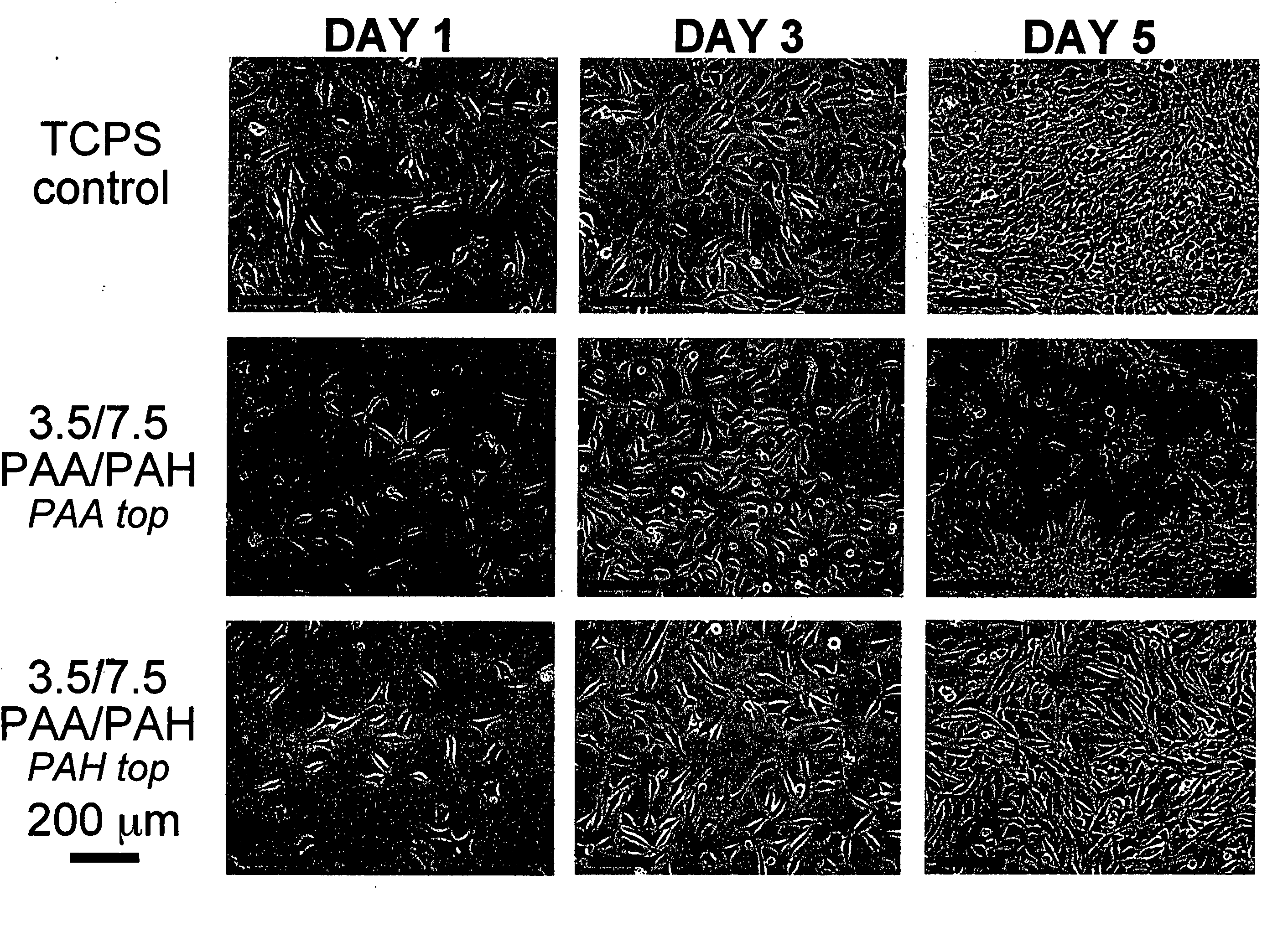
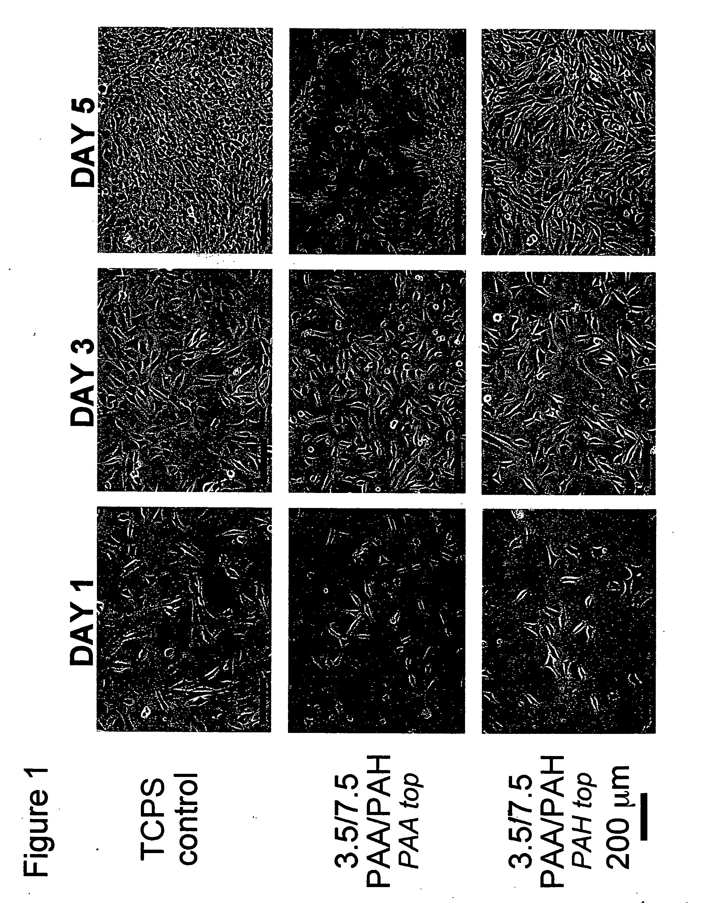
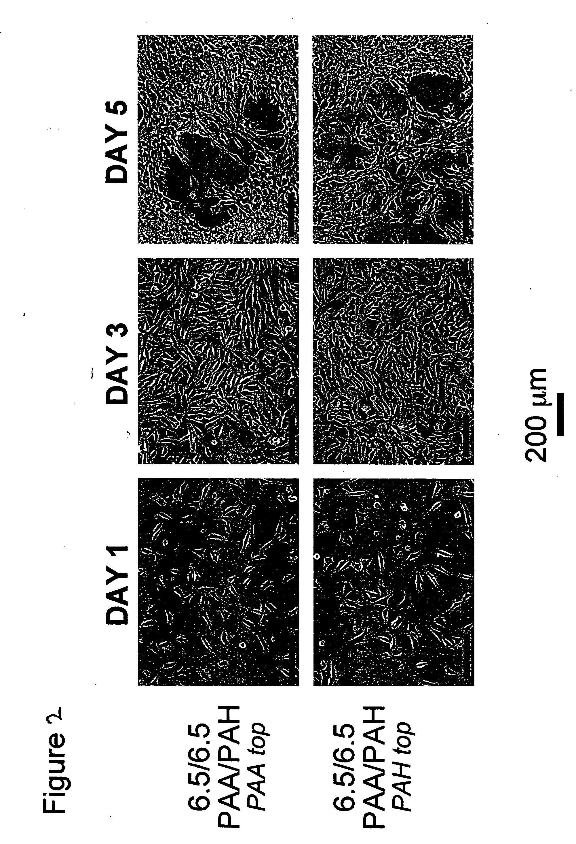

Image

  • Polyelectrolyte multilayers that influence cell growth methods of applying them, and articles coated with them
  • Polyelectrolyte multilayers that influence cell growth methods of applying them, and articles coated with them
  • Polyelectrolyte multilayers that influence cell growth methods of applying them, and articles coated with them

Examples


example 1

Materials

[0105] Poly(acrylic acid) (PAA) (MW˜90,000, 25% aqueous solution), poly(methacrylic acid) (PMA) (MW˜100,000), and polyacrylamide (PAAm) (MW˜800,000, 10% aqueous solution or 5,000,000, 1% aqueous solution) were obtained from Polysciences. Poly(allylamine hydrochloride) (PAH) (MW˜70,000), sulfonated poly(styrene), sodium salt, (SPS), (MW˜70,000), poly(diallyldimethylammonium chloride) (PDAC) (MW˜100,000-200,000) as a 20 wt. % solution, the methylene blue dye, and the rose bengal dye were purchased from Aldrich Chemical. The polymers were used without any further purification. Lysozyme (from chicken egg white, E.C. 3.2.1.17) and fibrinogen (fraction I, type I-S from bovine plasma, E.C. 232-598-6) were obtained from Sigma and prepared as 1 g / L and 0.2 g / L solutions, respectively, in Dulbecco's phosphate buffered saline (PBS) (pH˜7.4, with calcium and magnesium).

[0106] All polymer solutions were prepared as 10−2 M solutions (based on the repeat unit molecular weight) using de...

example 2

Preparation of Polyelectrolyte Multilayer Thin Films

[0109] All polyelectrolyte multilayer thin films were deposited directly onto tissue culture polystyrene (TCPS) petri dishes and multiwell plates (Falcon), TCPS slides (Nalgene), polished silicon wafers (Wafemet), glass slides (VWR Scientific), and ZnSe crystals (SpectraTech) at room temperature via an automatic dipping procedure using an HMS programmable slide stainer from Zeiss, Inc. The TCPS substrates were first immersed in the polycationic solution (e.g., PAH) for 15 minutes followed by rinsing in 3 successive baths of deionized neutral water (pH≈5.5-6.5) with light agitation, for 2, 1, and 1 minute(s), respectively. The substrates were then immersed into the oppositely charged polyanionic solution (e.g., PAA, PMA, or SPS) for 15 minutes and subjected to the same rinsing procedure. This process was repeated until the desired number of layers was assembled, after which the coated substrates were removed from the automatic di...

example 3

Film Thickness

[0111] The thickness and refractive index of the multilayer films deposited onto silicon were measured using a Gaertner ellipsometer, operating at 633 nm.

Film Roughness and Morphology

[0112] Atomic force microscopy (AFM, Digital Instruments Dimension 3000 Scanning Probe Microscope, Santa Barbara, Calif.) was used in tapping mode with Si cantilevers for surface morphology profiling and roughness measurements (dry state) of sample films built on silicon. Typically, square images of 1×1, 5×5, or 10×10 μm2 images were obtained for samples using a scanning rate of ˜1-1.5 Hz, a setpoint ˜1-1.5 V, and a resolution of 512 samples / line.

UV-visible Spectroscopy

[0113] Samples assembled onto glass substrates were immersed in either the methylene blue solution (prepared as a 10−3 M solution in Millipore water, adjusted to pH˜7.0) or the rose bengal dye solution (10−3 M solution in Millipore water, adjusted to pH˜5.0) for 15 min followed by 3 successive deionized neutral water...


PUM

PropertyMeasurementUnit
Temperatureaaaaaaaaaa
Fractionaaaaaaaaaa
Fractionaaaaaaaaaa

Abstract

One aspect of the present invention relates to a method of coating a surface, comprising sequentially depositing on a surface, under pH-controlled conditions, alternating layers of polymers to provide a coated surface, wherein a first polymer is selected from the group consisting of pH dependent cationic polyelectrolytes and neutral polymers, and a second polymer is selected from the group consisting of anionic polyelectrolytes, thereby permitting or preventing cell adhesion to said coated surface. In certain embodiments, the aforementioned method provides a coated surface to which cell adhesion is permitted. In certain embodiments, the aforementioned method provides a coated surface to which cell adhesion is prevented. Another aspect of the present invention relates to a method of rendering a surface cytophilic, comprising the step of coating a surface with a polyelectrolyte multilayer film, which film swells to less than or equal to about 150% of its original thickness when exposed to an aqueous medium. Another aspect of the present invention relates to a method of rendering a surface cytophobic, comprising the step of coating a surface with a polyelectrolyte multilayer film, which film swells to greater than or equal to about 200% of its original thickness when exposed to an aqueous medium.

Description

RELATED APPLICATIONS [0001] This application claims the benefit of priority to U.S. Provisional Patent Application Ser. No. 60 / 336,269, filed Oct. 25, 2001; and U.S. Provisional Patent Application Ser. No. 60 / 402,257, filed Aug. 9, 2002.GOVERNMENT FUNDING [0002] The invention was made with support provided by the National Science Foundation and the MRSEC program of the National Science Foundation; therefore, the government has certain rights in the invention.BACKGROUND OF THE INVENTION [0003] The ability to control the interaction of living cells with the surface of synthetic medical implants is a major goal in biomaterials research today, since the performance of any implant depends strongly on the compatibility at the materials-physiological interface. A new paradigm in biomaterials has emerged recently—to eliminate non-specific protein and cell attachment to implants and instead to direct the specific adhesion of certain cells. The ability to engineer the interactions of cells wi...

Claims


Application Information

Patent Timeline
IPC IPC(8): A61L27/34A61L27/50A61L29/08A61L31/10
CPCA61L27/34A61L27/50A61L2420/02A61L31/10A61L29/085
Inventor RUBNER, MICHAEL F.MENDELSOHN, JONAS D.YANG, SUNG Y.
Owner RUBNER MICHAEL F
Learn More