
Thermo-mechanical property enhancement plies for CVI/SiC ceramic matrix composite laminates

Inactive Publication Date: 2005-08-25
GENERAL ELECTRIC CO
View PDF25 Cites 11 Cited by
  • Summary
  • Abstract
  • Description
  • Claims
  • Application Information

AI Technical Summary

Benefits of technology

[0006] One embodiment of the present invention is directed to an improved ceramic matrix composite laminate including at least two lamina of directional, continuous ceramic fiber preforms. A layer of nonwoven mat construction includes a plurality of chopped fibers mixed with a bonding agent. The chopped fiber layer is interposed between at least two directional, continuous ceramic fiber preform lamina as to form an fiber reinforced interface and to reduce inter-laminar porosity formed between the adjacent directional, continuous ceramic fiber preform lamina.
[0008] One advantage of the composite construction of the present invention is that it is an inexpensive approach to improving interlaminar mechanical and thermo-mechanical material properties and reducing interlaminar porosity by preventing a continuous, stratified matrix rich interface layer in the laminate.
[0010] A further advantage of the hybridized directional, continuous ceramic fiber and chopped fiber non-woven composite laminate construction of the present invention is that the nonwoven layers sandwiched between interwoven layers are compatible with conventional directional, continuous ceramic fiber lamina lay-up techniques.

Problems solved by technology

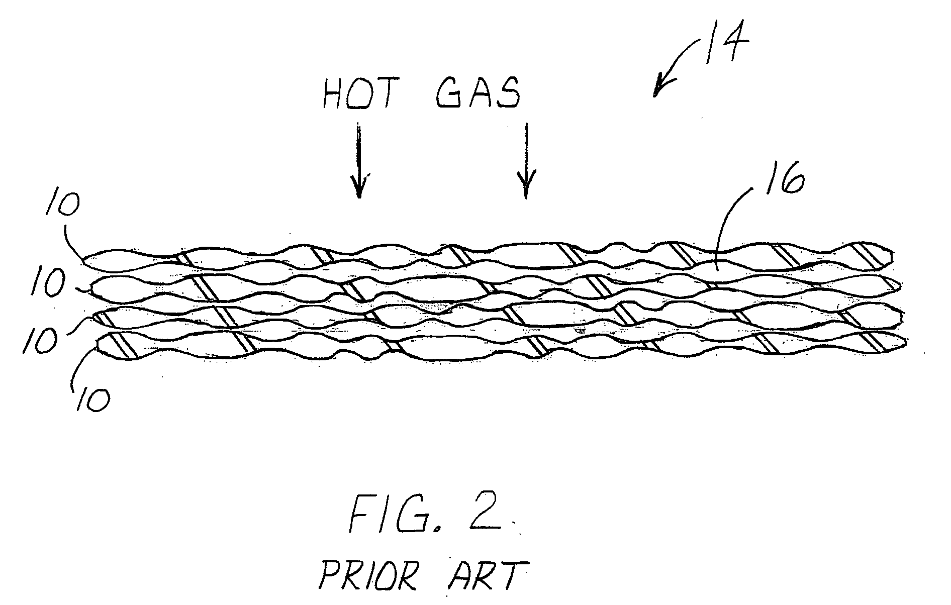
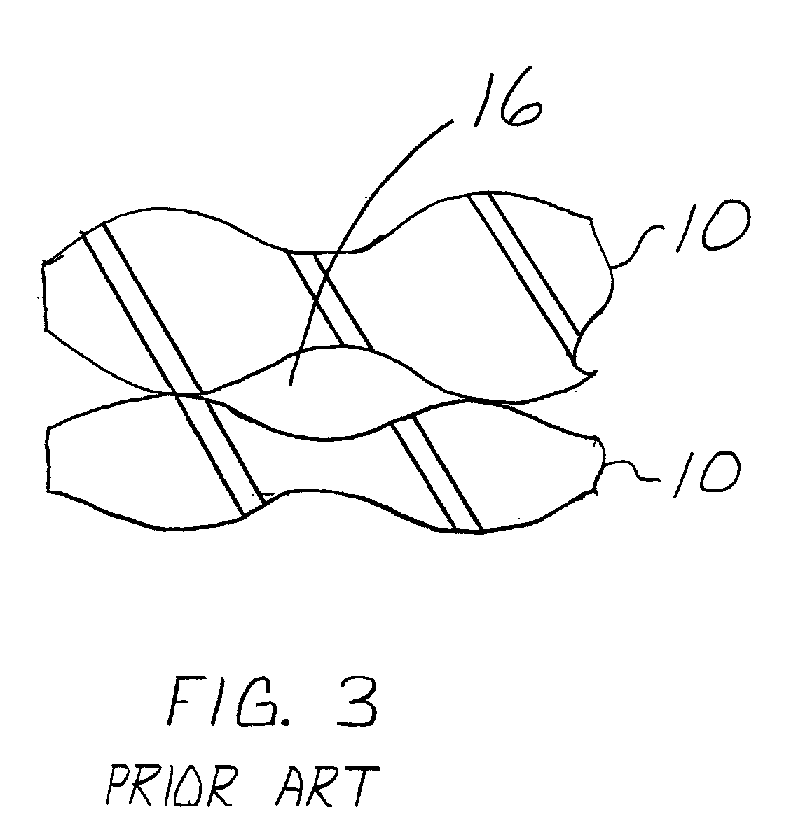
This interface typically includes a planar gap therebetween, also referred to as an inter-laminar gap, which is typically SiC matrix rich and porous, resulting in poor composite material performance properties at the porous, matrix-rich interface is substantially lacking in reinforcing ceramic fiber material.
This poor composite material performance is also due to the use of the woven continuous fiber plies and the corresponding “lumpiness” of the fabric, results in proportionately large inter-laminar pores.

Method used


Image

  • Thermo-mechanical property enhancement plies for CVI/SiC ceramic matrix composite laminates
  • Thermo-mechanical property enhancement plies for CVI/SiC ceramic matrix composite laminates
  • Thermo-mechanical property enhancement plies for CVI/SiC ceramic matrix composite laminates

Examples


Embodiment Construction

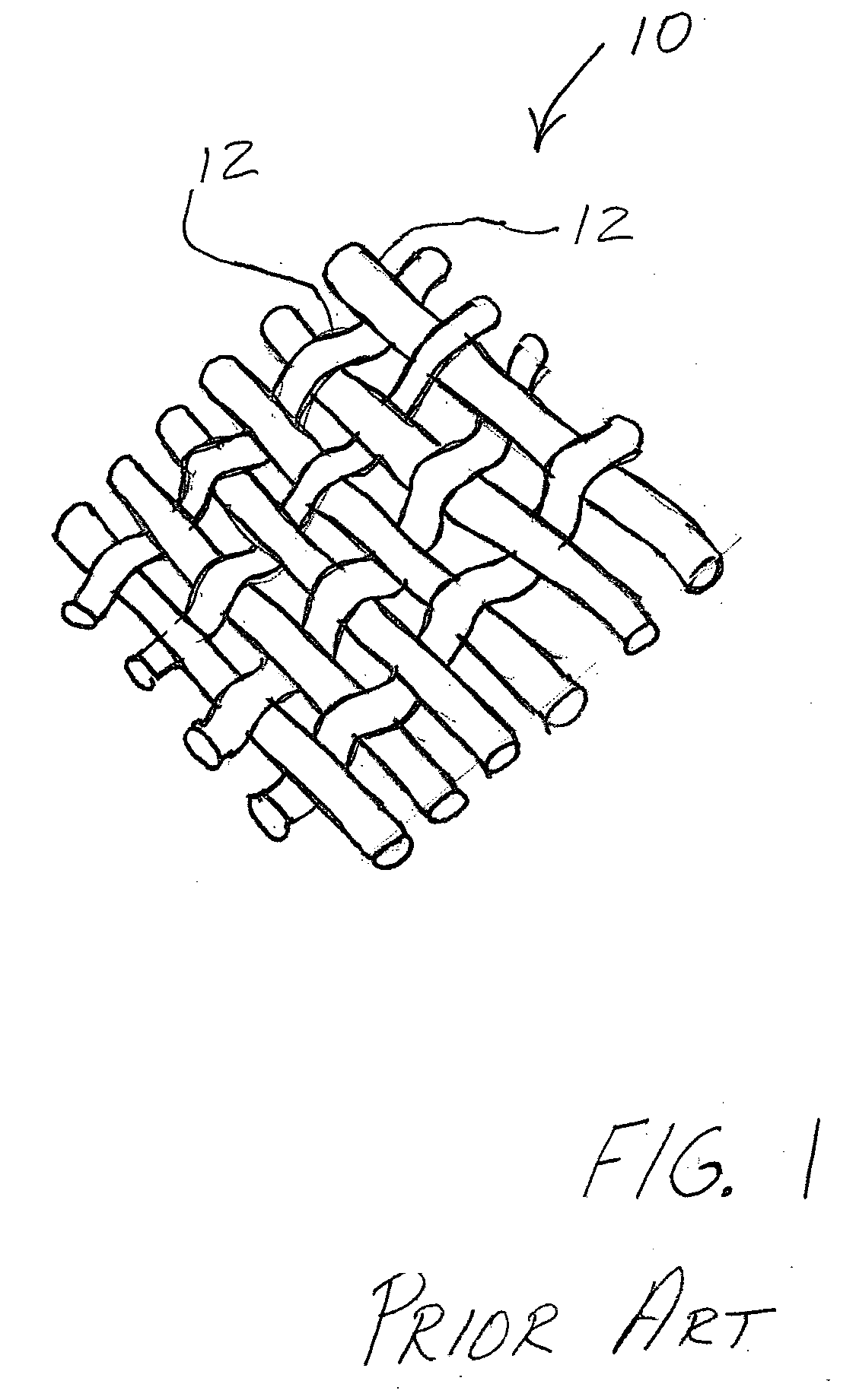
[0019] A typical composite construction to which the invention can be applied is illustrated, by means of example, in FIG. 1. Typically, textile preformed SiC fiber / SiC matrix composite laminates are fabricated with laminates or plies 10 comprised of woven or braided directional, continuous ceramic fiber lamina into a dry ply lay-up. SiC fiber, in the form of continuous fiber tow 12, is woven or braided (i.e., plain weaves, five harness satin weaves, tri-axial braids, etc.) to fabricate the plies 10 or dry laminae. These plies are then cut to shape and typically manually placed to form a layered fiber preform structure. The preform structure is placed on tooling to conform to the size and shape of the tooling and prepared for matrix densification. Other composite constructions utilize unidirectional plies, that is, the continuous fiber plies are aligned in a single direction. However, the angular orientation of the continuous fiber plies can be changed ply to ply to provide enhanced...


PUM

PropertyMeasurementUnit
Lengthaaaaaaaaaa
Thicknessaaaaaaaaaa
Thicknessaaaaaaaaaa

Abstract

A ceramic matrix composite laminate includes at least two directional, continuous ceramic fiber preform lamina each being formed of interwoven or braided fibers. A layer of non-woven mat includes a plurality of chopped ceramic fibers mixed with a bonding agent. The non-woven mat layer is interposed between adjacent directional, continuous ceramic fiber preform lamina to substantially eliminate inter-laminar gaps formed between the adjacent directional, continuous ceramic fiber preform lamina. The additional chopped fiber content improves the interlaminar mechanical and thermo-mechanical material properties of resulting ceramic matrix composite laminate.

Description

BACKGROUND OF THE INVENTION [0001] The present invention relates generally to a ceramic matrix composite construction and method for making same. Specifically, the present invention relates to an improved ceramic matrix composite construction and method for making same, the construction significantly improving inter-laminar mechanical and thermo-mechanical properties and increased resistance to inter-laminar cracking. [0002] Ceramic matrix composite materials (CMCs) comprising laminated plies of continuous ceramic fiber fabric lamina in a ceramic matrix to form laminates are often used due to their high strength to weight ratio and high temperature capability. The pedigree, or fabrication history of the material, directly affects the final part performance, including baseline thermo-mechanical properties. Conventional fabrication approaches employ a lay-up, which involves the stacking of directional, continuous ceramic fiber plies of material in a specified orientation and sequence....

Claims


Application Information

Patent Timeline
IPC IPC(8): B32B18/00C04B35/80
CPCB32B18/00C04B2237/704C04B35/80C04B35/806C04B2235/5244C04B2235/526C04B2235/5268C04B2237/38C04B35/63C04B35/63416C04B2237/32C04B2237/343C04B2237/365C04B2237/62C04B35/565Y10T442/608Y10T442/659Y10T428/249921Y10T442/67Y10T428/249928Y10T442/60Y10T442/605Y10T428/249953
Inventor KOSTAR, TIMOTHY DANIELDARKINS, TOBY GEORGE JR.CARPER, DOUGLAS MELTON
Owner GENERAL ELECTRIC CO
Learn More