
Magnetic thin film and magnetic head using the same

a magnetic head and thin film technology, applied in the direction of metal sheet core heads, instruments, data recording, etc., can solve the problems of difficult to control the magnetic anisotropy of the single fecon film, the magnetic flux density must be reduced, and the recording media develop the tendency to increase coercive forces, etc., to achieve high density recording

Inactive Publication Date: 2005-08-11
FUJITSU LTD
View PDF4 Cites 7 Cited by
  • Summary
  • Abstract
  • Description
  • Claims
  • Application Information

AI Technical Summary

Benefits of technology

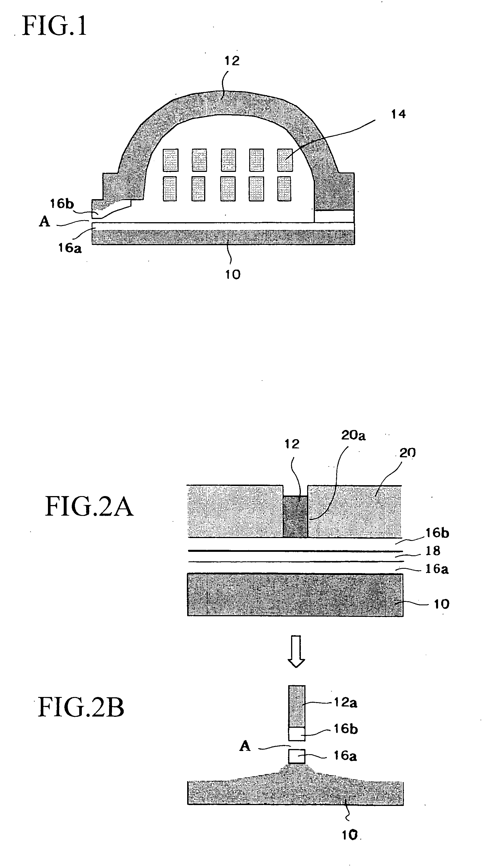
[0010] Each of the second constituting layers may be formed by reactive spattering using a reaction gas, such as N2 gas, O2 gas, after forming the first constituting layer. The second constituting layers is formed on each first constituting layer by reactive spattering, so that coarsening crystal grains can be restrained and the surface of the magnetic thin film can be flattened.
[0013] The magnetic head has a write-head whose front end section includes the magnetic thin film of the magnetic head, so the magnetic head can have high Bs and can be used for high density recording.

Problems solved by technology

In such small size range, a problem of thermal agitation of magnetic fine particles is realized, so that recording media develop tendency to increase coercive forces (Hc).
However, it is difficult to control magnetic anisotropy in the single FeCoN film, thus the FeCoN layer is formed on a base layer made of permalloy (Ni80Fe20) or sandwiched with permalloy layers so as to improve soft magnetism.
However, to make the specific resistance 50 μcm or more, amount of nonmagnetic elements must be increased, but the saturation magnetic flux density must be reduced, so it is difficult to obtain the high Bs value of 2.1T or more.
If this film is used as a seed layer of plating, abnormal deposition of a plating metal varies characteristics and thickness distribution of the plated films, further deformation of the magnetic pole lowers resolution of recording bits lower.
As described above, using the single FeCo alloy layer has many problems as to characteristics of a magnetic head.

Method used


Image

  • Magnetic thin film and magnetic head using the same
  • Magnetic thin film and magnetic head using the same
  • Magnetic thin film and magnetic head using the same

Examples


Embodiment Construction

[0017] Preferred embodiments of the present invention will now be described in detail with reference to the accompanying drawings.

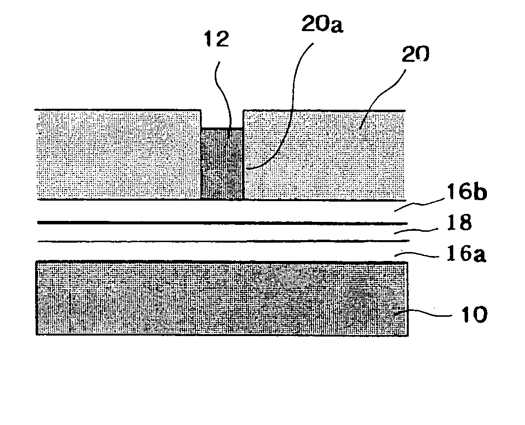
[0018]FIG. 1 is an explanation view showing a sectional structure of a write-head part of a magnetic head. In the drawing, a symbol 10 stands for a lower magnetic pole, a symbol 12 stands for an upper magnetic pole and a symbol 14 stands for a coil. The lower magnetic pole 10 and the upper magnetic pole 12 are made of a ferromagnetic material, e.g., NiFe. End faces of the lower magnetic pole 10 and the upper magnetic pole 12, which face a recording medium, are separated with a gap A, which acts as a write-gap. The gap A is included in a front section of a write-magnetic pole, and high Bs magnetic films 16a and 16b are respectively provided on inner faces of the lower magnetic pole 10 and the upper magnetic pole 12, which are mutually faced with the gap A. Data are recorded in the recording medium by magnetic fluxes leaked in the gap A from the end faces ...


PUM


Abstract

The present invention relates to a magnetic thin film, which has high saturation magnetic flux density Bs of 2.2T or more, which is formed into a flat surface having surface roughness of 5 nm or less and which is capable of preferably being used for a write-head, and a magnetic head. The magnetic thin film includes a FeCo-based alloy layer stacked with a different layer so as to obtain the surface roughness of 5 nm or less. When forming the FeCo-based alloy layer, it is possible to flatten the film surface by performing reactive spattering using a reaction gas such as N2 for each of the layers forming the multi-layered thin film.

Description

FIELD OF TECHNOLOGY [0001] The present invention relates to a magnetic thin film and a magnetic head using the same, more precisely relates to a magnetic thin film, which has high saturation magnetic flux density Bs of 2.2T or more, which is formed into a flat surface having surface roughness of 5 nm or less and which is capable of preferably being used for a write-head, and a magnetic head using the same. BACKGROUND TECHNOLOGY [0002] Sizes of recording bits have been made smaller to several hundreds nm or less with increase of surface recording density of recording media used for magnetic disk drive units, have been increased, and the sizes will be further smaller in the future. In such small size range, a problem of thermal agitation of magnetic fine particles is realized, so that recording media develop tendency to increase coercive forces (Hc). On the other hand, front end sections of magnetic poles are made narrower, so strong write-magnetic fields must be generated, further ma...

Claims


Application Information

Patent Timeline
IPC IPC(8): G11B5/31
CPCG11B5/3103G11B5/3163G11B5/3109
Inventor IKEDA, SHOJIKUBOMIYA, TAKAYUKIMATSUOKA, MASAAKITAGAWA, IKUYAKANE, JUNICHICHIKAZAWA, AKIFUMIHOSONO, KAZUMASA
Owner FUJITSU LTD
Learn More