
Silica sol gel micro-laser on a substrate and method of fabrication

Inactive Publication Date: 2005-08-04
CALIFORNIA INST OF TECH
View PDF26 Cites 28 Cited by
  • Summary
  • Abstract
  • Description
  • Claims
  • Application Information

AI Technical Summary

Benefits of technology

[0014] In a further alternative embodiment, is a method of making an ultra narrow line width micro-laser on a substrate, such as a chip or a wafer. The method includes providing a substrate and a doped solution, applying a coating of the doped solution to the substrate, forming an optical coating, forming

Problems solved by technology

However, challenges remain with integrating such devices on a chip or silicon substrate.
For example, spherical micro-resonators are difficult to integrate with planar silicon substrates as a result of their shape.
Additionally, silica micro-resonators that are made on a silicon substrate may present certain processing and integration challenges.
Thus, the other chip components and materials are exposed to the same heating temperatures and durations, including the underlying silicon substrate, which has a lower melting point of about 1400° C. Consequently, the silicon substrate may melt at temperatures that are used to process silica micro-resonators, causing the silica micro-resonator structure to fall or be damaged due to the instability of the underlying melted silicon.
Known implementation techniques, however, are typically expensive and ineffective since they implant a dopant on a surface or down to a limited depth of the micro-cavity.
Consequently, the implanted ions have a limited impact since they may only interact with a fraction of the optical energy stored in the resonator.
Sol gel materials have been used to form resonators, but with unacceptable results, for example, low Q factors.

Method used


Image

  • Silica sol gel micro-laser on a substrate and method of fabrication
  • Silica sol gel micro-laser on a substrate and method of fabrication
  • Silica sol gel micro-laser on a substrate and method of fabrication

Examples


Embodiment Construction

[0028] This specification describes embodiments of sol gel micro-lasers, such as silica sol gel micro-lasers, using undoped and doped sol gel solutions, and methods for making such micro-lasers. In the following description, reference is made to the accompanying drawings, which show by way of illustration, but not limitation, specific embodiments that can be utilized.

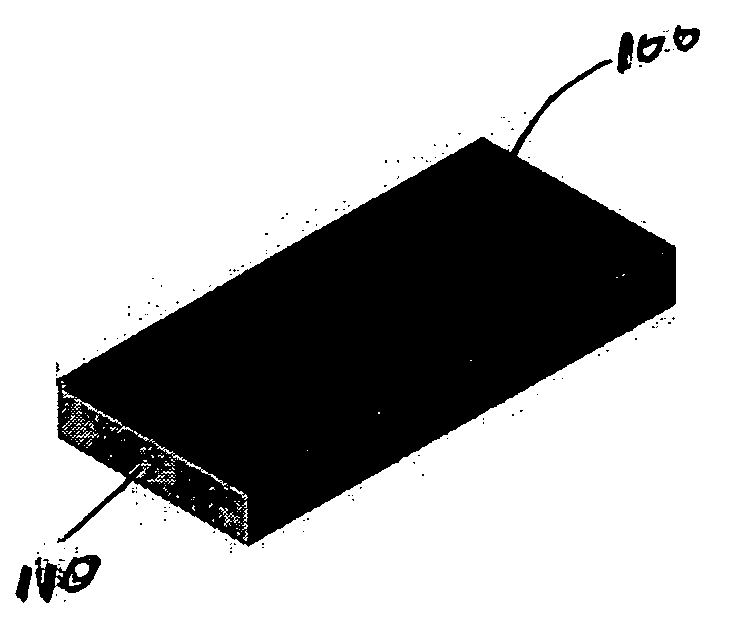
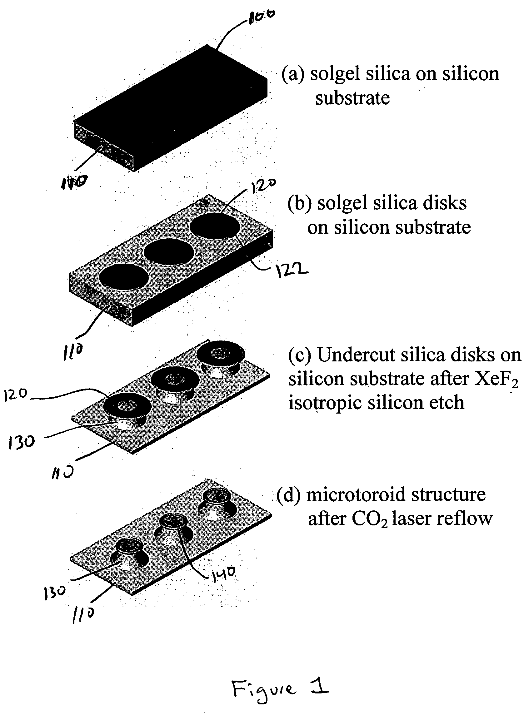
[0029] Referring to FIGS. 1 and 2, a silica sol gel solution 100 is applied to a substrate 110, such as a silicon substrate, a wafer or a chip, in order to form a silica sol gel coating. While other substrates can be utilized with various embodiments. This specification generally refers to a silicon substrate for purposes of explanation, but not limitation.

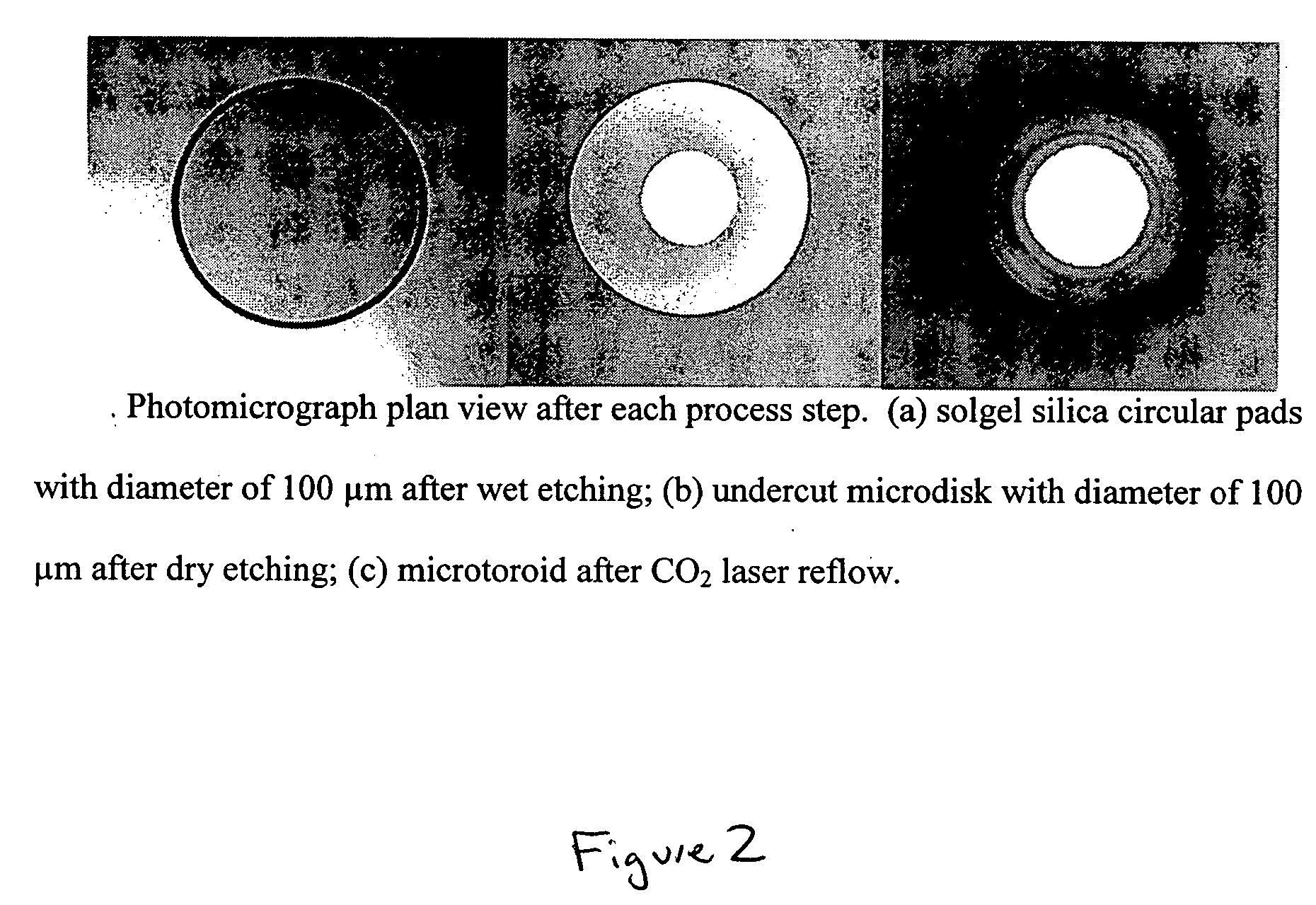
[0030] An etching process is used to form or shape silica sol gel disks 120 from the coating on the substrate 110. After the silica sol gel disks 120 are formed, the silicon substrate 110 is etched. As shown in FIG. 1, sections of the silicon substrate 110 underneat...


PUM


Abstract

Silica sol gel micro-lasers and methods of fabricating micro-lasers on a chip or a wafer. A silica sol gel micro-laser includes a silica sol gel optical micro-cavity, a substrate, and a support member or pillar that extends between the micro-cavity and the substrate. An outer surface or periphery of the micro-cavity extends beyond a top of the sol gel support member or is overhanging with respect to the underlying support member. Optical energy travels along an inner surface of the silica sol gel micro-cavity. Undoped silica sol gel micro-cavities can be used for Raman lasers. Sol gel micro-cavities can be doped with, for example, erbium, and can be used for erbium-doped micro-lasers that have ultra narrow line widths, for example, less than 100 Hz. Undoped and doped silica sol gel micro-lasers can have Q factors greater than 107.

Description

CROSS-REFERENCE TO RELATED APPLICATION [0001] This application claims priority under 35 U.S.C. §119 to U.S. Provisional Patent Application No. 60 / 541,110, filed Feb. 2, 2004, the entire disclosure of which is incorporated herein by reference, as though set forth in full.STATEMENT REGARDING FEDERALLY SPONSORED RESEARCH [0002] The U.S. Government has certain rights in this invention pursuant to Grant No. N00014-00-1-0650 awarded by the Office of Naval Research.FIELD OF THE INVENTION [0003] The present invention relates to micro-cavity resonators or micro-lasers, more particularly, to silica sol gel micro-cavity resonators and methods of fabrication. BACKGROUND OF THE INVENTION [0004] Various micro-cavity resonators or micro-lasers have been utilized to re-circulate light and store optical power. In a typical micro-cavity resonator, light traverses around an interior surface of the cavity. The optical power stored in the resonator can be used in cavity quantum electrodynamics (cQED), p...

Claims


Application Information

Patent Timeline
IPC IPC(8): H01S3/06H01S3/083H01S3/14H01S3/16H01S3/17H01S3/207H01S3/23H01S5/10
CPCH01S3/0604H01S3/0627H01S3/083H01S3/1603H01S5/1042H01S3/1611H01S3/17H01S3/207H01S3/2383H01S3/1608
Inventor VAHALA, KERRY J.YANG, LAN
Owner CALIFORNIA INST OF TECH
Learn More