Eureka AIR delivers breakthrough ideas for toughest innovation challenges, trusted by R&D personnel around the world.

Oil contaminated substrate treatment method and apparatus

Inactive Publication Date: 2005-07-07
RACIONAL ENERGY & ENVIRONMENT
View PDF23 Cites 41 Cited by
  • Summary
  • Abstract
  • Description
  • Claims
  • Application Information

AI Technical Summary

Benefits of technology

[0017] The present invention is directed to the discovery of a distillation method and apparatus for treating a substrate contaminated with oil for environmental disposal. Where desired, the process provides for the pretreatment of the substrate with an emulsion breaker,

Problems solved by technology

Hazardous waste is considered a threat to the environment due to the risk of surface and subsurface water pollution, air pollution, and interrupting the equilibrium of the ecosystem.
These formulations are generally expensive, which is the reason for recirculating them.
As the contaminated oil-based drill cuttings lose water, they become stickier in nature.
Thus, drill cuttings can be considered hazardous waste, depending on the residual components of the mud and their concentrations.
Encapsulation is rarely used because of the high risks involved since there is no guarantee of 100% encapsulation nor is there a guarantee that encapsulation will last over a long period of time under any environment at the final disposal site.
Biochemical degradation, as disclosed in U.S. Pat. No. 5,039,415 to Smith, requires constant supervision and control during the entire process, and this option is time consuming and treatment may take several years in each case.
Controlled landfill is less and less attractive since the problem is not solved, and only changes the place and time for ultimate resolution.
Additionally, this method of treatment may not be attractive for offshore drilling applications.
The main limitation for incineration lies in the operational costs and process control difficulties due to tight stoichiometric operating ranges that are hard to maintain when contaminant concentrations are variable.
Moreover, the incineration process is energy intensive because the entire matrix has to be heated to combustion temperatures, and many of the constituents have high thermal coefficients.
Furthermore, flexibility to set up incineration equipment in the field is low and the logistical costs are high.
Thermal desorption, as disclosed in U.S. Pat. No. 5,228,804 to Balch, U.S. Pat. No. 5,272,833 to Prill et al. and U.S. Pat. No. 5,927,970 to Pate et al., presents several limitations, including low thermal efficiency, poor process control, low flexibility, high investment and operating costs, and low feasibility for in situ projects.
The thermal efficiency of thermal desorption process is even lower than for incineration since the entire matrix is exposed to indirect heating, creating additional investment, maintenance and operational costs, along with poor process control.
The viscoelastic characteristics of drill cuttings make processing difficult because of a tendency for the drill cuttings to stick to walls and other equipment surfaces, thereby reducing thermal transmission by effectively decreasing the inner diameter of the drum with less productivity and / or quality.
Furthermore, thermal desorption requires additional treatment for the recovered gases, by condensation or other means of treatment, further increasing the cost.
The main focus of this approach is to delay hydrolysis of the lime until well after the mixture is blended to favor oxidation / hydrolysis of the organic contaminants, and as a consequence the process is relatively slow and not continuous.

Method used


Image

  • Oil contaminated substrate treatment method and apparatus
  • Oil contaminated substrate treatment method and apparatus
  • Oil contaminated substrate treatment method and apparatus

Examples


example

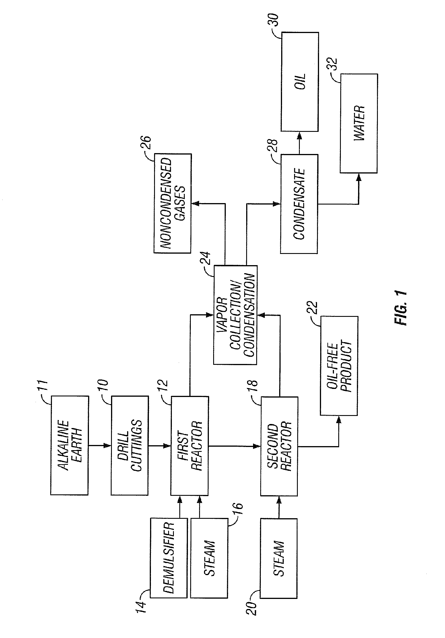
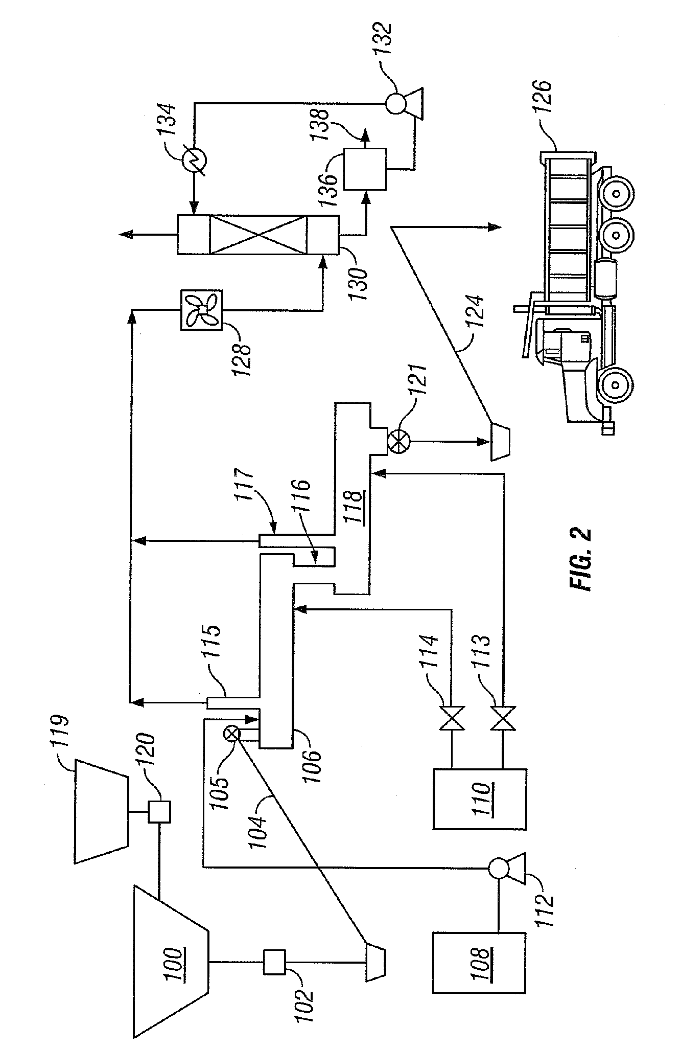
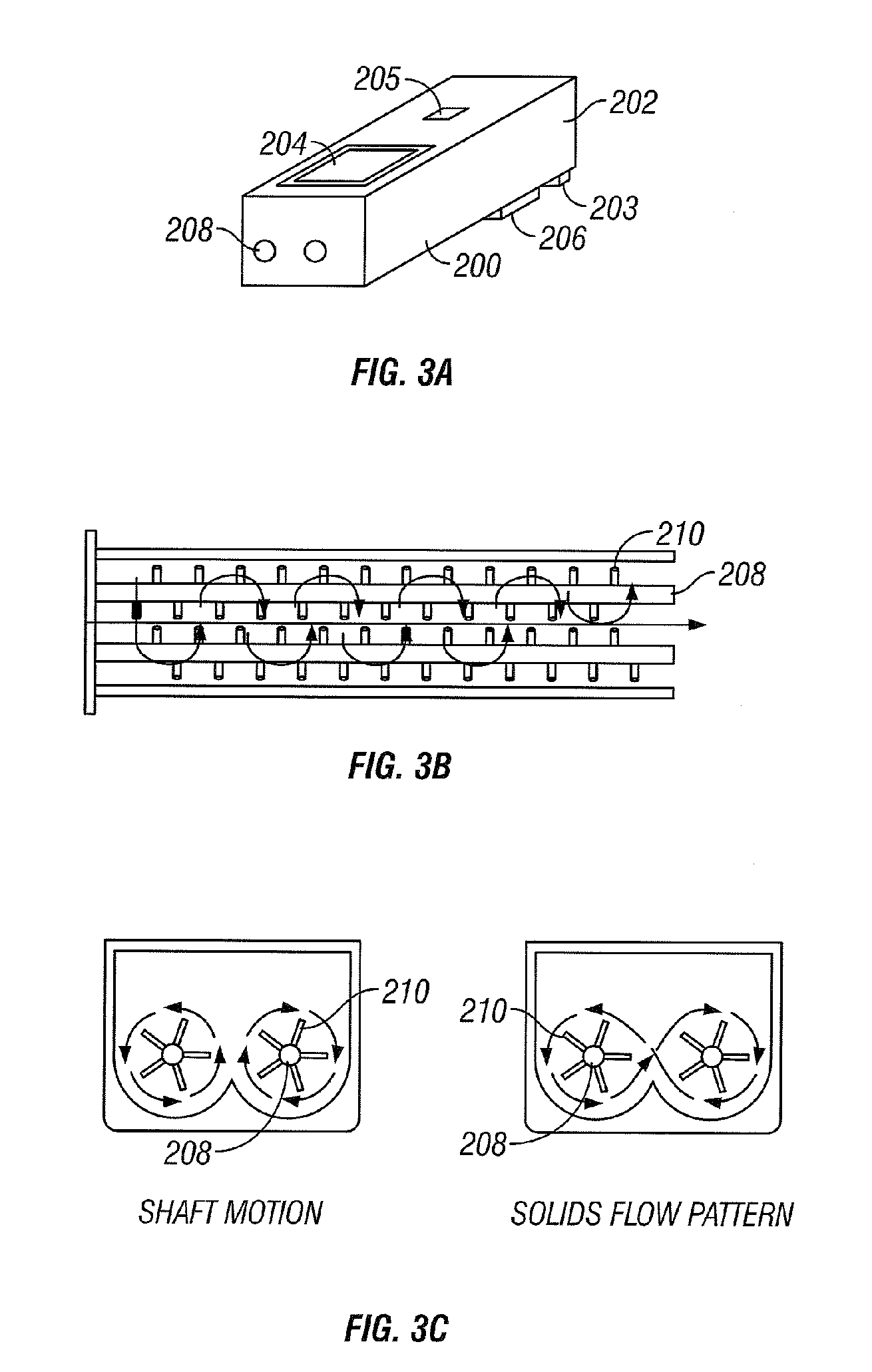
[0067] A test of the process and apparatus is conducted to treat drill cuttings contaminated with an oil-based drilling mud. The cuttings have an oil content of approximately 13% and a pH of approximately 11.0. The cuttings are supplied at ambient temperature and are continuously processed at a rate of 900 kg / h (2000 lb / h) (15 kg / min; 30 lb / min) two mixing stills arranged in series, each having a capacity of approximately 200 liters (40 gal), twin parallel shafts approximately 2 m (5 ft) in length with 25 paddles / shaft and a 0.2 m (0.7 ft) diameter and a tip speed of at least 3 m / s (7 ft / s). The average residence time of the cuttings in each mixing still is approximately 80 seconds. Steam is continuously added at approximately 30 psi (200 KPa) to an inlet adjacent the outlet of the first mixing still at a rate of 2 kg / min (4 lb / min), and the temperature in the first mixing still is maintained at greater than 100° C. (212° F.) near the outlet. A second steam source is continuously in...


PUM


Abstract

A method and apparatus for treating for disposal oil contaminated substrates, such as drill cuttings from drilling with an oil-based mud, by steam distillation. If necessary, the contaminated substrate 10 can be pretreated with an emulsion breaker 14. The contaminated substrate 10 can be treated with steam 16 in a first mixing still 12. The substrate can be optionally treated with a second steam source 20 in a second mixing still 18. The steam provides heat to vaporize the oil, moisture to treat the substrate and water to the reaction mixture. Recoverable constituents in the vapor can be condensed in a vapor collection system 24. The treated substrate 22 is essentially free of oil and can have a controlled water content. The process exhibits low energy consumption, rapid treatment, compact equipment and a high degree of process control.

Description

CROSS REFERENCE TO RELATED APPLICATION [0001] This application claims priority to U.S. Provisional Application Ser. No. 60 / 481,611 filed in the United States Patent and Trademark Office on Nov. 7, 2003.FIELD OF THE INVENTION [0002] This invention relates to the thermal treatment of solid substrates contaminated with oil for the environmentally acceptable disposal, and more particularly to the treatment of the drill cuttings with steam, and an optional organic demulsifier, for the purpose of rapidly removing oil from the drill cuttings to obtain treated drill cuttings essentially free of oil. [0003] Oil-based drill cuttings are generally regarded as controlled or hazardous waste. As such, the drill cuttings can be disposed of in two different ways: (1) decontamination treatment; or (2) hazardous waste controlled landfill. Hazardous waste is considered a threat to the environment due to the risk of surface and subsurface water pollution, air pollution, and interrupting the equilibrium...

Claims


Application Information

Patent Timeline
IPC IPC(8): B01D3/38B09B3/00B09C1/06C10G1/02E21B21/06
CPCB01D3/38B09B3/00E21B21/066B09C1/06C10G1/02B09B3/0083B09B3/40E21B21/06
Inventor CORDOVA, RAMON PEREZ
Owner RACIONAL ENERGY & ENVIRONMENT
Why Eureka
Eureka Blog
Learn More