
Reticle carrier

a technology of reticles and carriers, applied in the field of reticle carriers, can solve the problems of reticles being dislodged from their proper positioning before, unacceptably diminished or even unusable finished integrated circuit devices, scratching or other physical damage to reticles, etc., to minimize the chance of surface damage, less precise, and greater margin of error

Inactive Publication Date: 2005-06-23
ENTEGRIS INC
View PDF2 Cites 3 Cited by
  • Summary
  • Abstract
  • Description
  • Claims
  • Application Information

AI Technical Summary

Benefits of technology

[0006] The present invention provides a means of properly positioning a reticle in a carrier for engagement by reticle restraints while minimizing the opportunities for surface damage to the reticle inflicted by the reticle restraints. Also, with the present invention, manual positioning of the reticle on the reticle supports may be less precise, allowing for a greater margin for error.

Problems solved by technology

It is critically important that the surfaces of the reticle, especially the coated surface, be protected from damage or contamination, since any such defects or contamination may be projected onto the photoresist layer during exposure, thus leading to a finished integrated circuit device of unacceptably diminished or even unusable quality.
A problem, however, has been that a person initially manually positioning the reticle on the support surfaces may fail to place the reticle in the proper position for engagement by the restraint members, or may inadvertently cause the reticle to be dislodged from its proper positioning before it is engaged by the restraint members.
If the reticle is out of position a sufficient distance, the restraint members may then engage the reticle on its surfaces rather than at its edges, thereby causing scratching or other physical damage to the reticle.

Method used


Image

  • Reticle carrier
  • Reticle carrier
  • Reticle carrier

Examples


Embodiment Construction

[0020] The accompanying Figures depict embodiments of the reticle carrier of the present invention, and features and components thereof. Any references to front and back, right and left, top and bottom, upper and lower, and horizontal and vertical are intended for convenience of description, not to limit the present invention or its components to any one positional or spacial orientation. Any dimensions specified in the attached Figures and this specification may vary with a potential design and the intended use of an embodiment of the invention without departing from the scope of the invention.

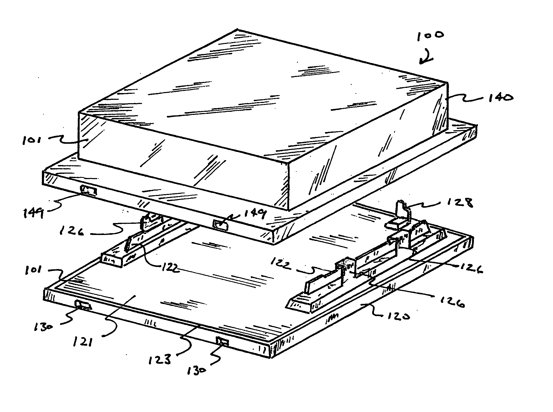
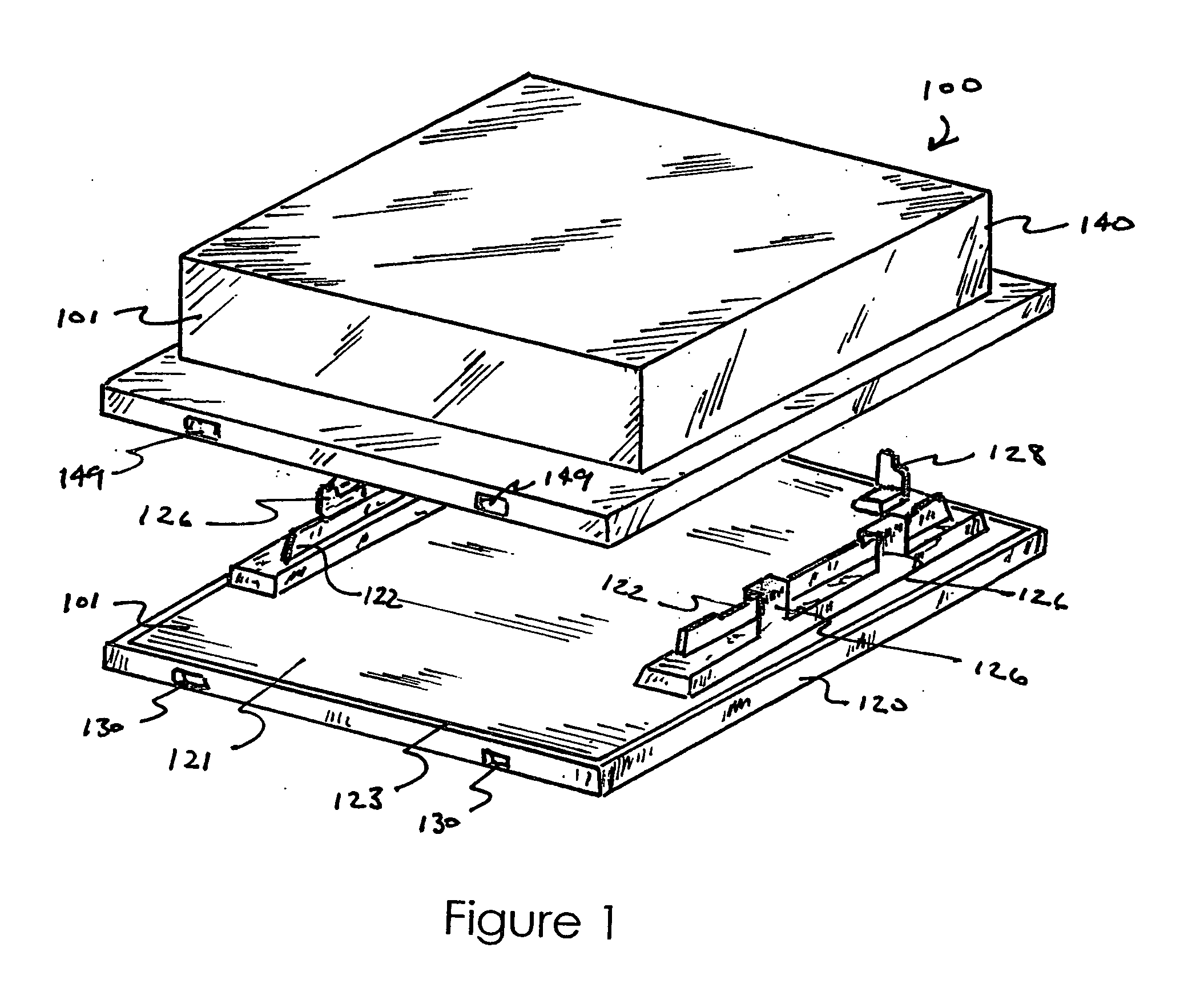
[0021] In FIGS. 1-10, there is shown a preferred embodiment of the self-positioning reticle carrier 100 of the present invention. Reticle carrier 100 generally comprises an enclosure 101 formed by mating base portion 120 with cover portion 140.

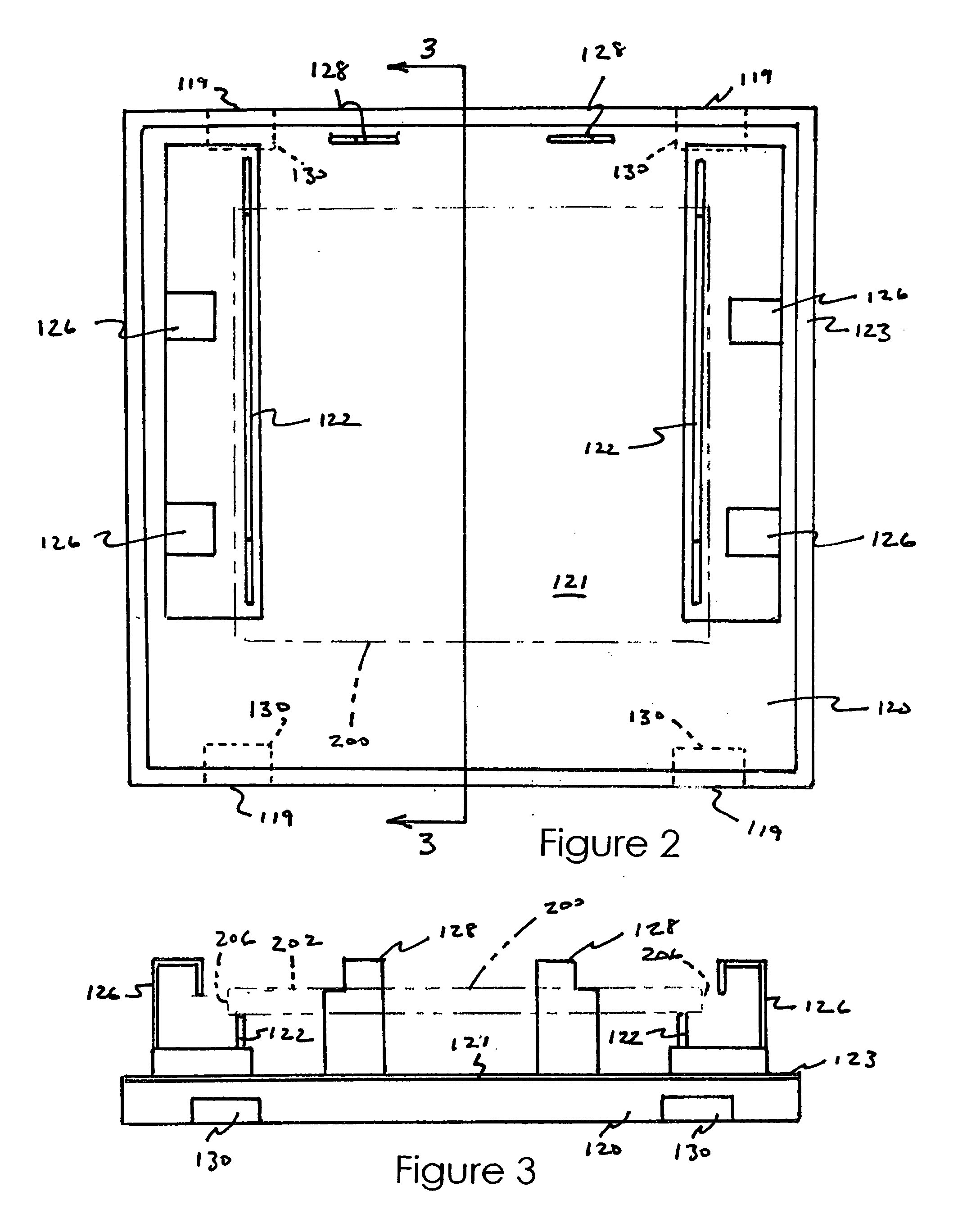
[0022] Base portion 120, shown best in FIGS. 2 and 3, has reticle supports 122 projecting upwardly from planar backing portion 121. Reticle side posi...


PUM


Abstract

A carrier for a reticle used in photolithographic semiconductor processing, having a base portion and a cover portion. The base portion has a plurality of reticle supports and a plurality of reticle positioning members. The cover portion is adapted to sealingly mate with the base portion, and has an inner surface with a plurality of spaced apart reticle restraints and a pair of reticle positioning tabs projecting inwardly therefrom. Each reticle positioning tab has a diagonal edge portion, and is oriented so that the diagonal edge portion urges a reticle resting on the reticle supports into engagement with the reticle restraints when the cover portion is mated with the base portion.

Description

FIELD OF THE INVENTION [0001] The invention relates to carriers for reticles used in photolithographic integrated circuit production, and more specifically to features for self-positioning of a reticle within a reticle carrier. BACKGROUND OF THE INVENTION [0002] Integrated circuit devices are commonly manufactured using a process known as photolithography. In photolithography, a photoresist layer is first deposited on a wafer substrate. Radiant energy, such as ultraviolet light, is then projected onto the photoresist layer through a template in the form of a mask or reticle having the desired pattern. The photoresist layer is then developed to remove either the exposed portions or the unexposed portions, to form a resist mask on the substrate. The resist mask can then be used to protect underlying areas during later deposition or etching processes. [0003] An important component of the photolithographic apparatus is the reticle, which provides the pattern and layout corresponding to ...

Claims


Application Information

Patent Timeline
IPC IPC(8): G03B21/62G03F1/66G03F7/20
CPCG03B21/62G03F7/70983G03F7/70741G03F1/66
Inventor WISEMAN, BRIANSTRIKE, JUSTIN
Owner ENTEGRIS INC
Learn More