Inventoriable-object control and tracking system

a technology for controlling and tracking access to inventions, applied in the direction of individual entry/exit registers, mechanical actuation of burglar alarms, instruments, etc., can solve the problems of creating legal liability, other objects may be inherently dangerous, explosives and many medicines are inherently dangerous,

Inactive Publication Date: 2008-03-11
KEY CONTROL HLDG
View PDF97 Cites 28 Cited by
  • Summary
  • Abstract
  • Description
  • Claims
  • Application Information

AI Technical Summary

Benefits of technology

[0007]Briefly described, the present invention includes an inventoriable-object control and tracking system which limits access to an inventoriable-object, tracks activities performed related to the object, and automatically detects the absence of the object for an inordinate amount of time. More particularly, the present invention includes an inventory control and tracking system which couples an electronic device, having a unique identification code, to an inventoriable-object and interfaces the device to a remote controller through a novelly-designed interface to enable periodic, consistent, and accurate identification of the object's presence or absence.
[0008]In the preferred embodiments of the apparatus of the present invention, each of a plurality of inventoriable objects is coupled to an object identification assembly having an electronic device mounted to an interface member of the assembly. The electronic device stores a unique identification code which is invisible to the eye, but electronically readable upon supply of a proper sequence of signals to the electronic device. By associating each inventoriable object with a different electronic device and, hence, a different identification code, the system provides a unique, trackable identification code for each object. Each identification assembly is receivable by a connector comprised of opposed, self-aligning, spring contacts having separate portions which independently deflect to insure and maintain consistent electrical interaction of the electronic device and connector. Each connector is one of a plurality of connectors which are electrically attached to a backplane with one contact of each connector being electrically connected to a positive data line and the other contact of each connector being electrically connected to a negative return line. The positive-connected contacts are arranged on the backplane in columns, while the negative-connected contacts are arranged on the backplane in rows, thereby defining a row and column matrix arrangement of connectors in which each connector has an associated row and column address and is independently, electrically-addressable from the other connectors of the matrix arrangement. The plurality of connectors and backplane are offset relative to panel which defines a polarized slot or opening aligned with each connector (the combination of a slot, or opening, and a connector being referred to herein as a receptacle) for receipt of an object identification assembly. The polarized design of each slot and opening enables receipt of an object identification assembly in only one orientation, thereby insuring that an identification assembly is always properly oriented for receipt by a connector.
[0009]The rows and columns of contacts are, in accordance with the preferred embodiments of the present invention, electrically coupled to a local controller by flexible cabling which enables relative motion between the backplane and the local controller should such relative motion be necessary in a particular embodiment. The local controller includes an electrically addressable switch which controls the supply of electrical power to most of the electronic components of the local controller. The addressable switch has a unique address and must electronically receive its address before it allows the supply of electrical power to the remaining electronic components of the local controller, thereby minimizing the opportunity for unauthorized operation of the local controller. The local controller also includes row and column address decoding and access circuitry which enables the unique identification of and independent interaction between a remote controller and each of the plurality of connectors to allow reading of the identification code of an electronic device by the remote controller when the electronic device resides in a connector. The remote controller connects electrically to and communicates with the local controller, in a bi-directional manner, using a parallel computer interface commonly employed for communication between computers and printers. Signals, including output data from the electrical devices, are transferred through the parallel interface in a serial protocol instead of the parallel protocol typically employed for communication between most computers and printers. The remote controller includes a central processing unit and a storage device to enable receipt and storage of data from the local controller which is related to the presence or absence of an object identification assembly and, hence, an object from the backplane.
[0022]Still another object of the present invention is to rapidly locate a particular object.
[0029]Still another object of the present invention is to interface an electronic device, having a unique identification code, and a connector to enable accurate, repeatable reading of the identification code from the electronic device.

Problems solved by technology

Other objects may be inherently dangerous or create legal liability because unauthorized use of such an object can create a safety hazard for others.
For instance, explosives and many medicines are inherently dangerous if used or dispensed improperly by untrained individuals.
Also, unauthorized use or copying of keys to apartments or hotel rooms can enable theft of personal valuables and can create personal safety hazards to tenants and guests.
Regardless of the source of an object's value, its dangerous nature, or its potential for creating legal liability, business owners, landlords, and hotel proprietors have sought, over the years, to restrict access to the above-described objects, and others, by limiting their access to only those individuals who require access to the objects in order to perform their job functions.
Unfortunately, such manual apparatus and methods have met with limited success since they typically rely heavily on the thoroughness of humans to consistently follow designated procedures.
Also, such systems are often fraught with the potential for misuse and abuse due to the dishonesty of some individuals and the inability of the systems themselves to detect possible misuse and abuse.
By keeping the key overnight, a salesperson or cohort may steal a car (or items from a car) or a worker may return to an apartment complex during the night to burglarize a unit and, potentially, cause physical harm to a tenant.
Additionally, by keeping a key out of the locked container for a longer period of time than necessary without the knowledge of a manager or landlord, the key may be copied or become lost by the salesperson or maintenance worker.
The limited success and inherent problems of manual systems suggest the need for a system which automatically controls access to and tracks the use of various types of objects.
Therefore, the system had no way of detecting the presence or absence of an object unless the drawer was opened or closed, for example, by a manager or landlord.
Thus, the system could not accurately track the amount of time that an object was not present in the container, nor could it determine who actually had possession of the object.
Also, because the assemblies were not restrained and were therefore, prone to variable, random movement relative to the drawer and enclosure, misreads by the bar-code scanner were a continual problem requiring repeated openings and closings of the drawer to effect accurate reading of all of the bar-codes on the present assemblies.
Other problems, including dust and dirt present on the bar-codes, also caused misreads by the bar-code scanner.
Additionally, because the bar-codes were visible on the assemblies, they could be easily copied by an individual for the creation of substitute objects designed to “fool” the system, thereby compromising the security supposedly provided by the system.

Method used


Image

  • Inventoriable-object control and tracking system
  • Inventoriable-object control and tracking system
  • Inventoriable-object control and tracking system

Examples


Embodiment Construction

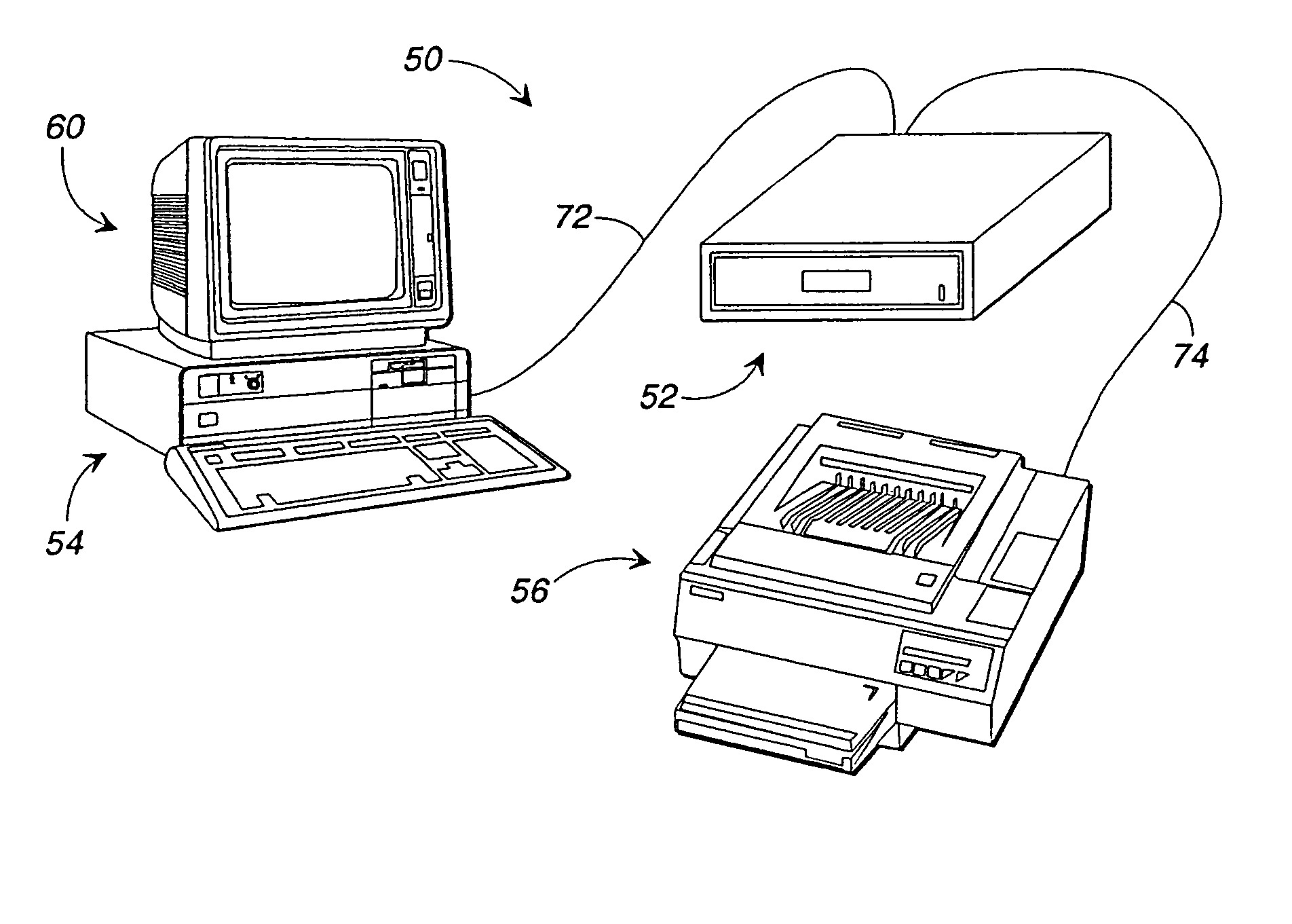
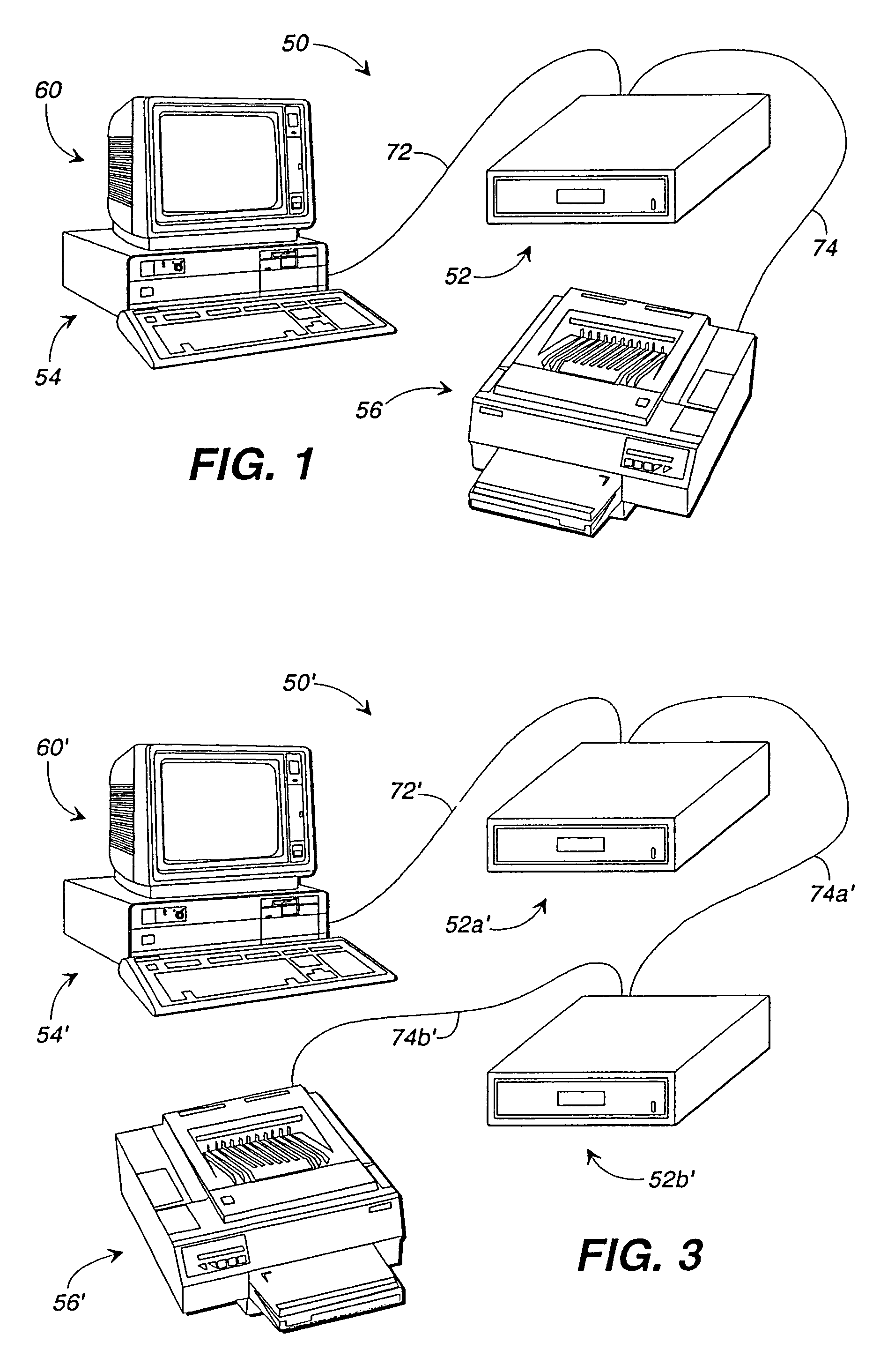
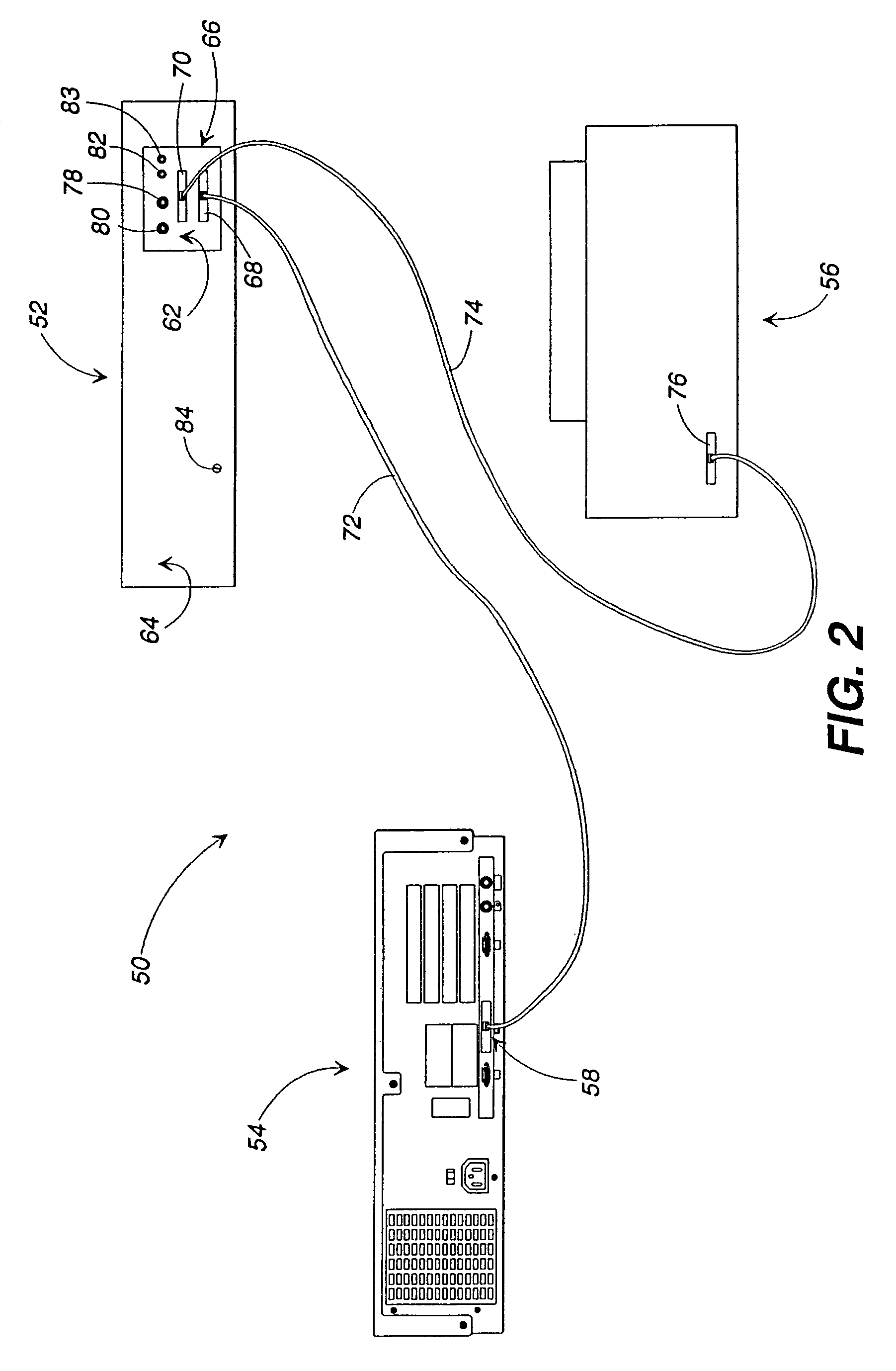
[0079]Referring now to the drawings, in which like numerals represent like components throughout the several views, an inventory control and tracking system 50, in accordance with the first preferred embodiment of the present invention, is displayed in FIGS. 1 and 2. The inventory control and tracking system 50 comprises an inventoriable-object storage unit 52 which is electronically interposed between a remote controller 54 and a printer 56. An example of a remote controller 54, acceptable in accordance with the present invention, is an IBM-compatible personal computer having a central processing unit, a hard disk drive, a random access memory, a keyboard, a video interface, and a parallel communications port 58 (or data communication interface 58). A video monitor 60 resides atop the remote controller 54 and receives video data for display to system users. The components of the remote controller 54 and video monitor 60 perform in accordance with their conventional functions, there...


PUM


Abstract

An inventoriable-object control and tracking system comprising, in accordance with its preferred embodiments, an object identification assembly having an electronic device, with a unique electronically-readable identification code, which is connected to an inventoriable-object to enable control over access to the object and tracking of the object to identify a user in possession of the object. The system further includes a row and column matrix of electrical connectors located offset from a panel defining a corresponding row and column matrix of polarized slots for receipt of a plurality of object identification assemblies in a single orientation. Each connector of a matrix of electrical connectors comprises a pair of opposed, spring contacts having independently-deflectable portions to insure proper electrical contact with an electronic device of each object identification assembly. The system also includes a local controller connected to the matrix of electrical connectors and to a remote controller which executes, in accordance with the preferred methods, a plurality of software routines that communicate bi-directionally using a serial protocol, via a parallel data communications interface, to acquire and process data from each object identification assembly present. In accordance with the preferred apparatus, the system additionally comprises a storage unit having a drawer which is withdrawable from an enclosure upon operation of an electronically-actuated locking mechanism. The storage unit includes a slot and electrical connector positioned in a drawer face plate assembly for receipt of a personal identification assembly which enables a user to gain access to the plurality of object identification assemblies residing in the storage unit.

Description

[0001]This application is a continuation of application Ser. No. 10 / 035,530, filed on Oct. 23, 2001 now U.S. Pat. No. 6,707,380, which is a continuation of Ser. No. 09 / 389,820, filed Sep. 3, 1999, now U.S. Pat. No. 6,317,044, which is a continuation of Ser. No. 09 / 073,757, filed May 6, 1998, now U.S. Pat. No. 6,075,441, which is a continuation of Ser. No. 08 / 708,617, filed Sep. 5, 1996, now U.S. Pat. No. 5,801,628, which claims benefit of Ser. No. 60 / 003,429, filed Sep. 8, 1995.FIELD OF THE INVENTION[0002]This invention relates generally to the field of controlling and tracking access to various types of objects, and in its most preferred embodiments, to integrating an electronic identification code and tracking system to continually inventory a plurality of objects.BACKGROUND OF THE INVENTION[0003]Many objects have intrinsic value of their own or have value because they enable access to other valuable objects. For instance, jewelry and coins have intrinsic value due to the value of...

Claims


Application Information

Patent Timeline
IPC IPC(8): G08B13/14G06F15/00G06F17/21G07C11/00G07F11/62
CPCG07C9/00896G07F9/026G07F11/62G08B13/1427G07C2009/00936
Inventor MALONEY, WILLIAM C.
Owner KEY CONTROL HLDG
Why Eureka
Try Eureka