
Image forming apparatus, image forming process, and process cartridge for image forming apparatus

Active Publication Date: 2005-06-16
RICOH KK
View PDF28 Cites 40 Cited by
  • Summary
  • Abstract
  • Description
  • Claims
  • Application Information

AI Technical Summary

Benefits of technology

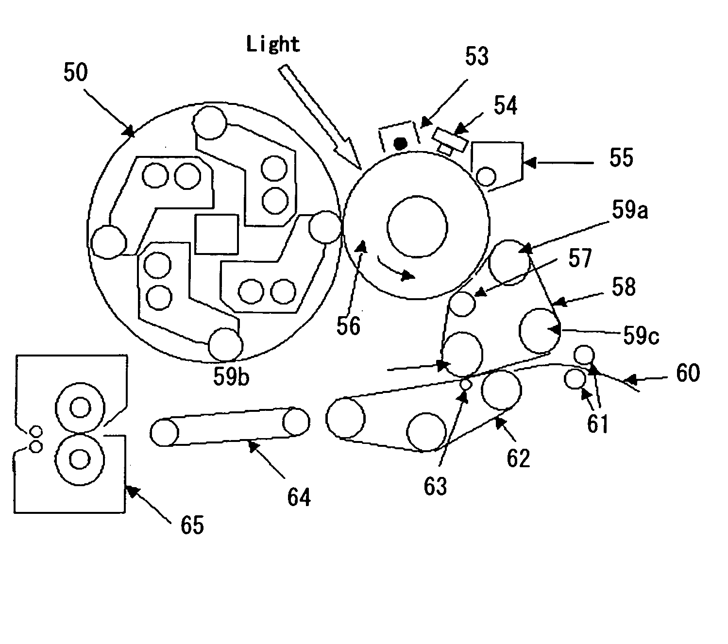
[0016] The objects of the present invention are to provide image forming apparatuses, image forming processes, and process cartridges for the image forming apparatuses, in which lower friction coefficient and lower surface energy of photoconductor surface may be maintained even in higher temperature conditions; voids or filming due to contaminant deposition caused by resin fine particles etc. at toner surface may be prevented; and superior images may be formed during prolonged period without extraordinary or abnormal images.
[0032] The reason is not clear, but is considered that the surface of the electrophotographic photoconductor is lowered in the friction coefficient and lower surface energy, therefore, adhesion of small amounts of resin fine particles in the toner onto photoconductor surface may be prevented; further, the polyalylate copolymer resin with higher wear resistance may bring about the condition that the polyalylate copolymer resin covers fluoropolymer fine particles with the aid of higher compatibility with fluoropolymer; thereby lowering of resistance near the fluoropolymer fine particles may be suppressed while maintaining the wear resistance.

Problems solved by technology

However, such toners for fixing at lower temperatures are not thermal resistant in general; therefore, they often solidify due to heat from associated apparatuses or heat at the preservation condition, thus so-called blocking or offset is often induced.
Accordingly, sufficient temperatures can hardly be assured for such toners; namely, toners for fixing at lower temperatures without such problems have not been attained yet even polyester resins are employed, which exhibit relatively superior thermal preservation ability while affording appropriate fixing ability at lower temperatures.
As such, thermal preservation ability and hot offset resistance are nowadays demanded for toners while maintaining lower fixing-initiating temperatures, such demands have been considered as inconsistent previously.
Such a toner may satisfy the aforesaid demand at least in part; however, some problems still remain, for example, extraordinary or abnormal images generate due to contaminant deposition or filming, induced possibly by resin fine particles for fixing ability at lower temperatures that may slightly remain on photoconductors; transfer efficiency decreases at transferring toner images on the photoconductor to transferring media, when image forming apparatuses are operated under high temperatures or the temperatures inside apparatuses comes to higher due to continuous operating.
However, such an additional mechanism inevitably leads to enlarged or complicated apparatus, resulting in cost-up and complicated maintenance.
On the other hand, the fluoropolymer fine particles tend to flocculate in the dispersion due to the inherent property of fluoropolymer, thus the uniform dispersion may be hardly prepared.
However, the surface layers that contain fluoropolymer fine particles disclosed in these references are mostly of lower content of fluoropolymer, thus the lower friction coefficient and lower surface energy may not possibly be maintained for long duration.
JP-A No. 6-130711 listed above discloses higher content of the fluoropolymer, but any descriptions appear in terms of particle size after dispersion; therefore, finely dispersing seems to be difficult due to the flocculating tendency induced by higher content of fine particles of the fluoropolymer.
Coated films formed from such coating liquid often result in excessive irregularity and localized existence of fluoropolymer fine particles on the coated surface.
Excessive irregularity of the coated surface often leads to inferior cleaning or deteriorated toner images.
Further, the localized fluoropolymer fine particles tend to yield micro areas with higher friction coefficient and higher surface energy and micro areas with lower friction coefficient and lower surface energy at the surface of photoconductors, which often causes inferior cleaning or deteriorated toner images.
Moreover, excessively large secondary flocculate size of fluoropolymer fine particles may lead to scattering of laser light on the flocculates, which often causes turbulence of exposed latent images or insufficient potential contrast due to insufficient light amount, resulting in extraordinary or abnormal images.
For the countermeasure, anti-oxidant agent may be added (see JP-A No. 8-292585 for example); however, a small amount of additive does not exhibit sufficient effect, whereas a large amount of additive may deteriorate electric properties.
Further, incorporation of polyalylate resin is proposed as binder resin of the surface layer (see JP-A No. 8-248666 for example); however, conventional mono-component polyalylate resins cannot provide a sufficient effect currently.
Accordingly, effective solution against the generation of extraordinary or abnormal images in continuous usage has not been found yet, as such.

Method used


Image

  • Image forming apparatus, image forming process, and process cartridge for image forming apparatus
  • Image forming apparatus, image forming process, and process cartridge for image forming apparatus
  • Image forming apparatus, image forming process, and process cartridge for image forming apparatus

Examples


example 1

of Photoconductor Production

[0243] A coating liquid for undercoat layer was prepared as follows: 150 parts of an alkyd resin (Becolite M6401-50, by Dainippon and Chemicals, Co.) and 10 parts of melamine resin (Super Beckamine G-821-60, by Dainippon and Chemicals, Co.) were dissolved into 150 parts of methylethylketone, and titanium oxide powder (Tie Pail CR-EL, by Ishihara Sangyo Co. Ltd.) was added to the solution, then the mixture was subjected to milling for 12 hours to prepare a coating liquid for undercoat layer.

[0244] The coating liquid was coated on an aluminum substrate of 90 mm in diameter by 392 mm in length, and dried at 130° C. for 120 minutes, to form an undercoat layer in 3.5 μm thick.

[0245] Then 4 parts of polyvinylbutyral resin (XYHL, by UCC Co.), having formula (1) shown below, was dissolved into 150 parts of cyclohexane.

[0246] Then, 10 parts of bisazo pigment was added to the silution, and was subjected to dispersion by means of a ball moll; then 210 parts of c...

example 2

of Photoconductor Production

[0252] Photoconductor 2 was prepared in the same manner as Photoconductor 1, except for changing the resin of formula (A) into the resin of formula (B). [0253] (l, m: mole ratio, l=0.32, m=0.68)

Comparative Example 1 of Photoconductor Production

[0254] Comparative Photoconductor 1 was prepared in the same manner as Photoconductor 1, except for changing the resin of formula (A) into the bisphenol Z type polycarbonate resin.


PUM

PropertyMeasurementUnit
Temperatureaaaaaaaaaa
Lengthaaaaaaaaaa

Abstract

Disclosed is an image forming apparatus for lowering friction coefficient and lowering surface energy of photoconductor surface in particular, which comprises an electrophotographic photoconductor, charging unit, light exposure unit, developing unit, transferring unit, and fixing unit, the electrophotographic photoconductor comprises a photosensitive layer on a conductive support and fluoropolymer fine particles at the outermost layer, a part of the fluoropolymer fine particles are exposed above the surface of the outermost layer in configurations of primary particles and secondary particles formed by flocculation of plural primary particles, and sum of area ratios of particles in the configurations of the primary particles and the secondary particles, each particles having an average diameter D of 0.15 μm≦D≦3.0 μm as respective projected figures of exposed portion above the surface of the outermost layer, is 10% to 60% based on the entire surface area of the outermost layer, and wherein the binder resin in the outermost layer comprises a polyalylate copolymer resin having a structural unit of alkylene-aryldicarboxylate.

Description

BACKGROUND OF THE INVENTION [0001] 1. Field of the Invention [0002] The present invention relates to image forming apparatuses, image forming processes, and process cartridges for image forming apparatuses, which are adapted for lowering friction coefficients and lowering surface energies of electrophotographic photoconductors in particular. [0003] 2. Description of the Related Art [0004] In the area of electrophotographic processes, various types have been proposed previously (see U.S. Pat. No. 2,297,691, Japanese Patent Application Publication (JP-B) No. 49-23910, and JP-B No. 43-24748, for example). Usually, in electrophotographic processes, electrostatic latent images are formed on photoconductors by various means along with making use of photoconductive substances, the latent images are developed using toner, the toner images are optionally transferred on paper, then the images are fixed by means of heating, pressing, solvent vaporization or the like, and images are formed. [00...

Claims


Application Information

Patent Timeline
IPC IPC(8): G03G5/147G03G9/08G03G9/097G03G15/01G03G21/00
CPCG03G5/147G03G9/097G03G9/0821G03G5/14726
Inventor TAKADA, TAKESHIIKEGAMI, TAKAAKISUGINO, AKIHIRO
Owner RICOH KK
Learn More