
Method for performing delta volume decomposition and process planning in a turning step-nc system

a step-nc system and process planning technology, applied in the direction of programme control, instruments, total factory control, etc., can solve the problems of delta volume decomposition that is not suitable for cutting with the cutting tool, needs post-processing, and system does not support an interface for inputting/outputting a cad fil

Inactive Publication Date: 2005-06-16
POSTECH ACAD IND FOUND
View PDF4 Cites 17 Cited by
  • Summary
  • Abstract
  • Description
  • Claims
  • Application Information

AI Technical Summary

Benefits of technology

[0005] It is, therefore, an object of the present invention to provide a method for decomposing a delta volume into smaller volumes based on not onl

Problems solved by technology

Since such a conventional method uses a relatively simple method for recognizing part geometry, it has disadvantage in that one part, which may be cut at once by using one cutting tool, is recognized as several subdivided parts.
Further, since the conventional method subdivides a delta volume (i.e., a volumetric difference between a raw stock and a part defining a material that must be cut away during the actual machining process) into smaller volumes without considering cutting tool characteristics, the decomposed delta volumes may not be suitable to be cut by using the cutting tool and, therefore, may need to be post-processed.
For example, commercial machining supporting systems equipped in a typical CNC system, Fanuc 15-TF of Fanuc, Inc. and Mazatrol T32-2 of Mazak, Inc., have a problem in that the systems do not support an interface for inputting / outputting a CAD file.
Further, in these systems, part geometry and process plans must be manually defined, and it is difficult to select a cutting tool for processing an uncut part.
However, it has disadvantage in that delta volumes must be defined manually since it does not define a concept of part geometry.

Method used


Image

  • Method for performing delta volume decomposition and process planning in a turning step-nc system
  • Method for performing delta volume decomposition and process planning in a turning step-nc system
  • Method for performing delta volume decomposition and process planning in a turning step-nc system

Examples


Embodiment Construction

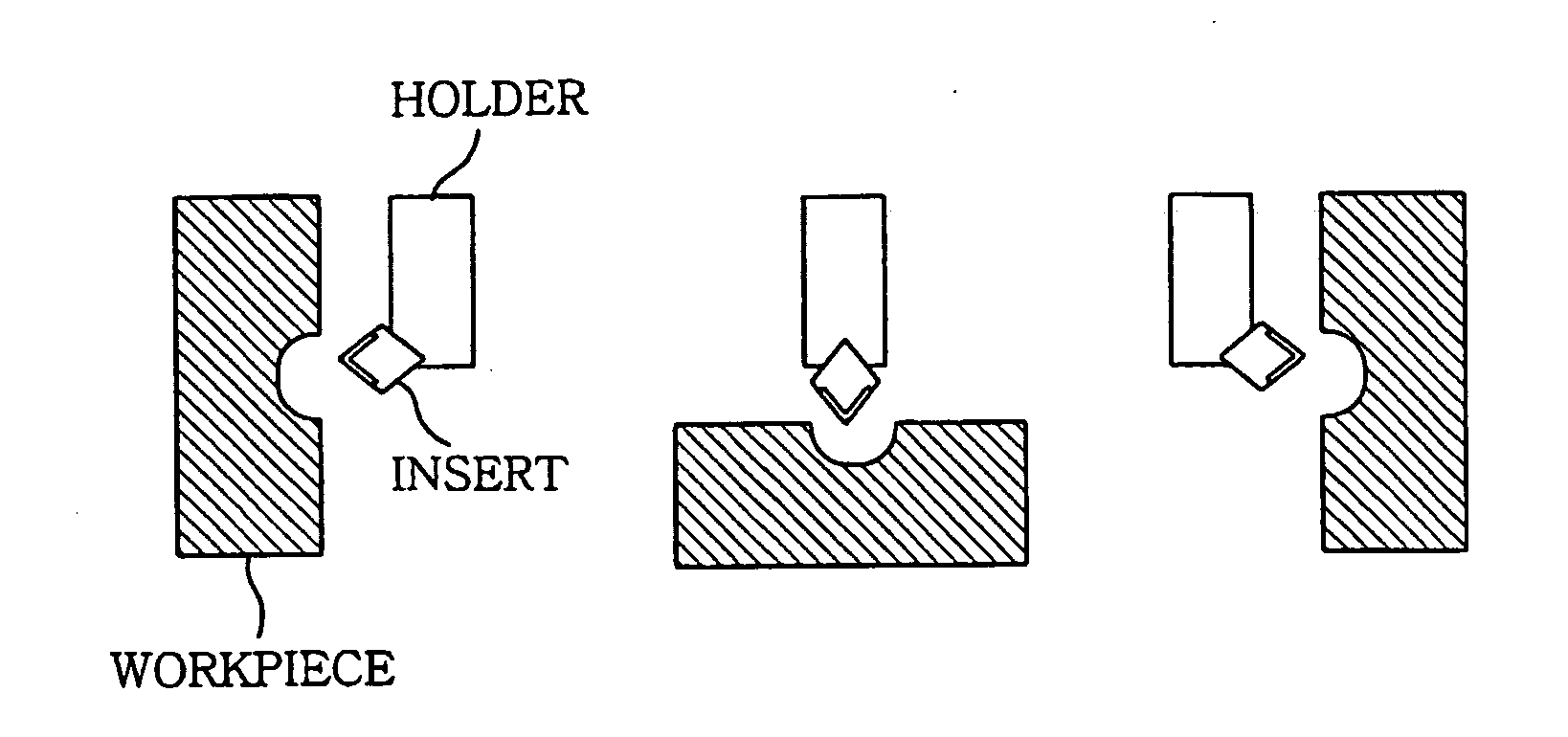
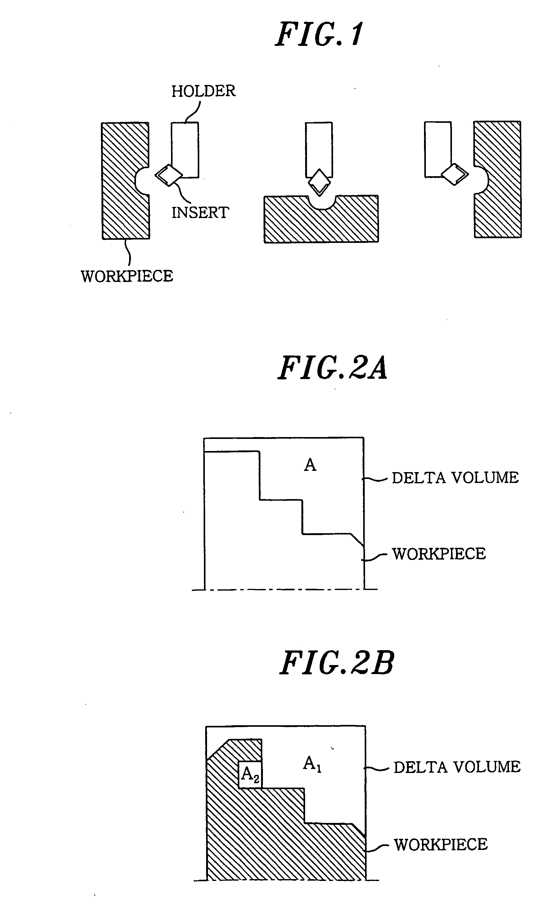
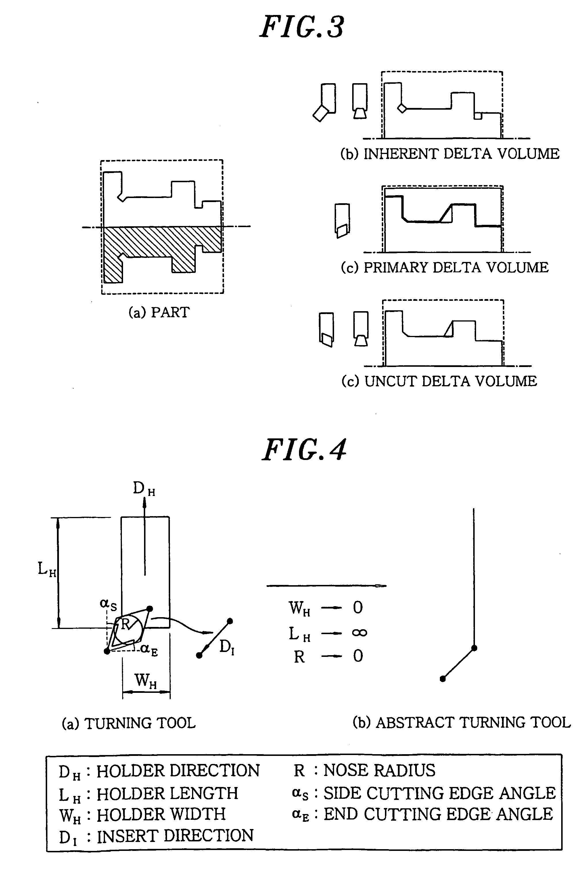
[0053] A finished part to be machined in a turning machine may be represented by using a profile thereof. A shape of a part, which is cut away during the turning process, varies depending on a cutting tool to be used in cutting the part. The recognition of the parts to be machined can be accomplished through a decomposing of a delta volume, i.e., a material that must be cut away during the actual machining process. Since the finished part is symmetric with respect to an axis and is cut by revolving the axis and moving a cutting tool two-dimensionally with respect to the axis, the delta volume can be represented by a two-dimensional profile thereof.

[0054] Turning characteristics to be considered in determining the delta volume are as follows. Firstly, a cutting tool must remove as much delta volume material as possible. Secondly, a delta volume is determined based on the type of the cutting tool. That is, in a raw stock, a feasibly cuttable volume and an uncut volume are determined....


PUM

PropertyMeasurementUnit
Volumeaaaaaaaaaa
Surface roughnessaaaaaaaaaa

Abstract

A profile of a finished part is recognized based on an inputted CAD data. A delta volume for the finished part is decomposed based on information on cutting tools and the profile. Thereafter, a dependency graph representing precedence relation between the decomposed delta volumes is generated. And then, a process sequence graph representing process plans is generated based on the dependency graph. The delta volume decomposition is performed based on information on cutting tools and a machine configuration as well as part geometry, such that the decomposed delta volumes are suitable to be cut away from a raw stock by the cutting tools.

Description

FIELD OF THE INVENTION [0001] The present invention relates to a method for automatically generating process plans for use in a turning machine; and, more particularly, to a method for decomposing a delta volume based on information on cutting tools and CAD data including geometry information on a finished part and, thereafter, based on the results of the delta volume decomposition, generating process plans for use in cutting a body of revolution in a turning machine. BACKGROUND OF THE INVENTION [0002] In general, a conventional method for automatically cutting mechanical parts in a turning machine generates a process plan based on information on the geometry of the mechanical parts without considering the characteristics of the actual turning process. The conventional method includes the steps of: (i) processing information on a profile of a finished part, which is inputted as a file; (ii) recognizing a part geometry based on the profile; and (iii) processing the recognized part ge...

Claims


Application Information

Patent Timeline
IPC IPC(8): B23Q15/00G05B19/4097
CPCG05B19/4097G05B2219/35097Y10T82/10G05B2219/35167G05B2219/35104Y02P90/02B23Q15/00
Inventor SUH, SUK-HWANCHEON, SANG-UKLEE, BYEONG-EON
Owner POSTECH ACAD IND FOUND
Learn More