Multi-channel radiometer imaging system

Inactive Publication Date: 2005-06-09
REVEAL IMAGING
View PDF25 Cites 21 Cited by
  • Summary
  • Abstract
  • Description
  • Claims
  • Application Information

AI Technical Summary

Benefits of technology

[0015] The radiometer of the present invention uses a combination of hybrid, low noise amplifiers (LNA's) and a switch to achieve low system temperature and low implementation cost. Unlike a typical Dicke radiometer where the switch losses translate directly into an increase in system noise, such as system temperature, the switch is positioned after a low noise amplifier. This design eliminates the impact of the switch losses. The radiometer of the present invention also combines the benefit of the low noise figure achieved by the hybrid approach and the simple, single channel processing achieved by the Dicke approach.

Problems solved by technology

The sensitivity of existing radiometer designs, however, has been limited to about 1 deg K, resulting in poor images.
The sensitivity of radiometer measurements are also often limited by random gain fluctuations in the RF front end, low frequency noise (l / f), and bias in the detector circuits.
Many of these proposals do not yield a true solution that will allow MMW radiometers to be commercially viable.
In addition, the high cost of MMW RF receivers has limited the number of channels in the radiometer to a low number, resulting in a requirement to scan both azimuth and elevation to create an image.
This radiometer system, however, requires processing of two channels, i.e., the antenna and reference, resulting in higher system complexity and cost.

Method used


Image

  • Multi-channel radiometer imaging system
  • Multi-channel radiometer imaging system
  • Multi-channel radiometer imaging system

Examples


Embodiment Construction

[0042] The present invention will now be described more fully hereinafter with reference to the accompanying drawings, in which preferred embodiments of the invention are shown. This invention may, however, be embodied in many different forms and should not be construed as limited to the embodiments set forth herein. Rather, these embodiments are provided so that this disclosure will be thorough and complete, and will fully convey the scope of the invention to those skilled in the art. Like numbers refer to like elements throughout, and prime notation is used to indicate similar elements in alternative embodiments.

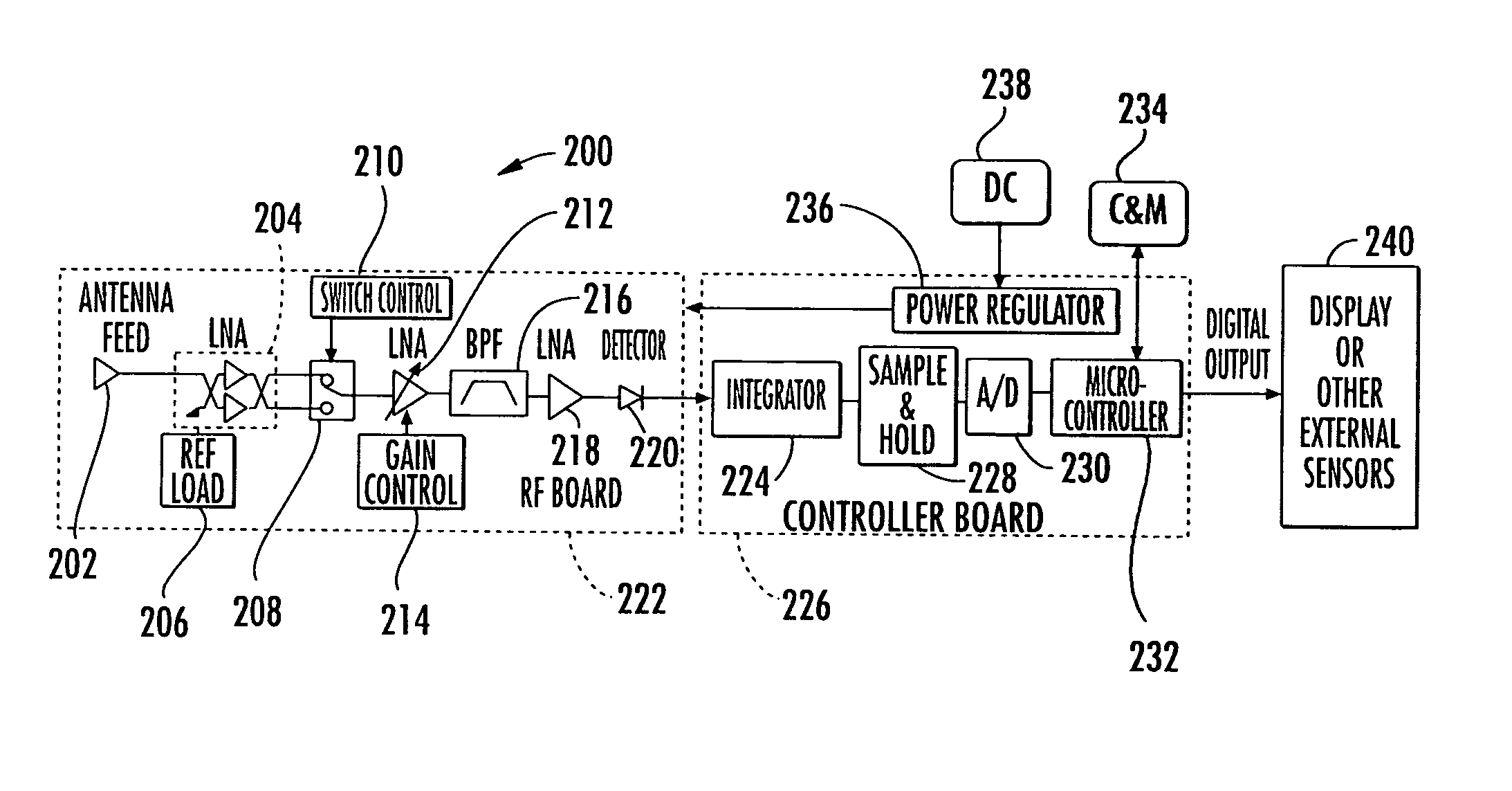
[0043] The present invention overcomes many existing shortcomings of current radiometers, including gain variation of the amplifiers, low frequency noise, detector bias, low sensitivity and high cost. The present invention reduces cost and size of a radiometer by a least a factor of ten and provides a commercial advantage over many current radiometers.

[0044] The low cost...


PUM


Abstract

A radiometer includes a housing and an RF board carried by the housing. A hybrid and amplifier circuit receives an unknown signal and a known reference signal. A switch receives signals as inputs from the hybrid and amplifier circuit and switches between the inputs. A detection circuit receives and detects the signal from the switch forming a detected signal. A controller board is carried by the housing and an integration circuit and processor receive the detected signal and produces a digital output.

Description

RELATED APPLICATIONS [0001] This application is a continuation-in-part of commonly-assigned patent application Ser. No. 10 / 847,892 filed May 18, 2004, which is based on provisional application Ser. No. 60 / 504,182 filed Sep. 18, 2003, the disclosures which are hereby incorporated by reference in their entirety.FIELD OF THE INVENTION [0002] The present invention relates to the field of focal plane radiometers, and more particularly, the present invention relates to radiometer systems applicable for use at millimeter wave (MMW) frequencies. BACKGROUND OF THE INVENTION [0003] Since radio waves may be considered infrared radiation of long wave, a hot body would be expected to radiate microwave energy thermally. In order to be a good radiator of microwave energy, a body must be a good absorber. The best thermal radiator is a “black body.” The amount of radiation emitted in the MMW range is 108 times smaller than the amount emitted in the infrared range. Current MMW receivers, however, hav...

Claims


Application Information

Patent Timeline
IPC IPC(8): G01K11/00
CPCG01K11/006H01L2224/48137H01L2924/01079H01L2924/14H01L2924/1423H01L2924/12032H01L2924/19041H01L2924/01019H01L2924/00
Inventor AMMAR, DANNY F.
Owner REVEAL IMAGING
Why Eureka
Try Eureka