Optical component using optical transmission element joining metal holder

Inactive Publication Date: 2005-05-12
MITSUBISHI ELECTRIC CORP +1
View PDF12 Cites 6 Cited by
  • Summary
  • Abstract
  • Description
  • Claims
  • Application Information

AI Technical Summary

Benefits of technology

[0014] It is an object of the invention to provide an optical component having a high reliability, in which a tensile stress is not applied to an optical transmission element when joining a metal holder, thus preventing cracks and separations from occurring in the optical transmission element.
[0015] An optical component of this invention is designed such that the circumferential wall of an optical transmission element partially joins a metal holder via a joining material, wherein a stress applied to the optical transmission element when joining the metal holder is normally directed in a compression direction of the optical transmission element, whereby it is possible to prevent cracks and separations from occurring in the optical transmission element. As a result, it is possible to prevent errors from occurring in optical characteristics, regardless of variations of the environmental temperature. Thus, it is possible to present the optical component having a high reliability.
[0016] The above can be evaluated by using a thermal expansion coefficient α1 of the optical transmission element, a thermal expansion coefficient α2 of the joining material, and a thermal expansion coefficient α3 of the metal holder. It is necessary to satisfy the relationship of α1<α2<α3 by adequately selecting materials for the optical transmission element, joining material, and metal holder, whereby when the optical transmission element joins the metal holder, the stress applied to the optical transmission element can be normally directed in the compression direction of the optical transmission element. Thus, even when the circumferential wall of the optical transmission element partially joins the metal holder, it is possible to reliably prevent cracks and separations from occurring in the optical transmission element.
[0018] The optical transmission element is inserted into a through hole that is formed to penetrate through the metal holder along the center axis, wherein a bank for keeping the joining material is actualized by a tapered portion, which is formed in proximity to one end of the through hole of the metal holder in relation to the optical transmission element, whereby it is possible to prevent the joining material from flowing into other portions other than the joining portion of the optical transmission element inserted into one end of the through hole of the metal holder. That is, the metal holder has the tapered portion serving as the bank, which is filled with a sufficient amount of the joining material. Thus, it is possible to produce the optical component that is superior in the joining strength with the metal holder and in the airtight property. Since this invention reliably prevents the joining material from flowing into other portions other than the joining portion of the optical transmission element inserted into one end of the through hole of the metal holder. This avoids the occurrence of abnormality in optical characteristics of the optical component; hence, it is possible to provide the optical component having a high reliability.
[0019] The tapered portion is slanted in an insertion direction of the optical transmission element, which is inserted into the through hole of the metal holder, whereby the thickness of the joining material is reduced along the inclination of the tapered portion. This allows the ‘melted’ joining material, which is made wet, to flow along the tapered portion of the metal holder due to gravity, whereby it is possible to improve the joining property of the metal holder joining the optical transmission element; hence, it is possible to produce an optical component that is superior in joining strength and airtight characteristics. When the optical transmission element is accompanied with an antireflection film (or AR coating), it is necessary that the joining temperature be lower than the heat-resistant temperature of the antireflection film.
[0024] As described above, this invention is directed to an optical component in which the circumferential wall of an optical transmission element partially joins a metal holder via joining material, wherein stress is normally applied to the optical transmission element in its compression direction. Thus, it is possible to avoid the occurrence of cracks and separations in the optical transmission element. As a result, even when the environmental temperature varies, it is possible to avoid the occurrence of errors in optical characteristics of the optical component; hence, it is possible to provide the optical component having a high reliability.

Problems solved by technology

The adhesive generally has a high hygroscopic property, so that optical device 40 using the adhesive may become fragile in certain environmental conditions.
In addition, the relatively low glass dislocation temperature reduces the use-allowable temperature range of the optical device 40 using the adhesive, and so-called “outgassing phenomenon” may occur.
This causes a problem in that optical devices using the adhesive do not meet long-term reliability.
The alloy solder composed of lead and tin has a relatively low melting point; therefore, when a certain load such as gravity is normally applied to the soldered portion of an optical device, a creeping phenomenon in which the solder becomes deformed over time may easily occur.
That is, when the optical transmission element 41 and the metal holder 42 are fixed together using the alloy solder, the position of the optical transmission element 41 may vary over time; therefore, it is very difficult to guarantee the stability of the optical system over a long time.
Furthermore, thermal fatigue may cause cracks in the solder so that the optical transmission element 41 may be varied in position and in optical axis.
However, it is difficult for the PbO—B2O3 material, which is normally used for the low melting point glass 53, to have a reduced burning temperature of 450° C. or less; that is, it is difficult for the burning temperature of the low melting point glass 53 to be decreased to be equal to the heat resistance temperature of the antireflection film 54 or less.
However, due to the intervention of the low melting point glass between the optical transmission element (e.g., an optical lens) and the metal holder in the optical device (or optical component) disclosed in the aforementioned documents, there is a problem in that the incoming light incident on the optical transmission element is varied in optical characteristics.
However, when a clearance portion between the optical transmission element and the metal holder is filled with the low melting point glass, the optical characteristics must be deteriorated.
When the optical transmission element joins the metal holder by using the joining material such as the low melting point glass, in other words, when the low melting point glass is affixed between the optical transmission element and the metal holder, cracks and double refraction may occur in the optical transmission element due to the stress based on the difference between the thermal expansion coefficients of the prescribed parts, which raises a problem in that a light extinction ratio must be deteriorated.
However, due to tensile stress caused by the combination of materials, cracks or separations may easily occur on the surface of the optical transmission element.

Method used


Image

  • Optical component using optical transmission element joining metal holder
  • Optical component using optical transmission element joining metal holder
  • Optical component using optical transmission element joining metal holder

Examples


Embodiment Construction

[0038] This invention will be described in further detail by way of examples with reference to the accompanying drawings.

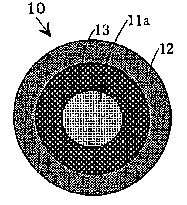
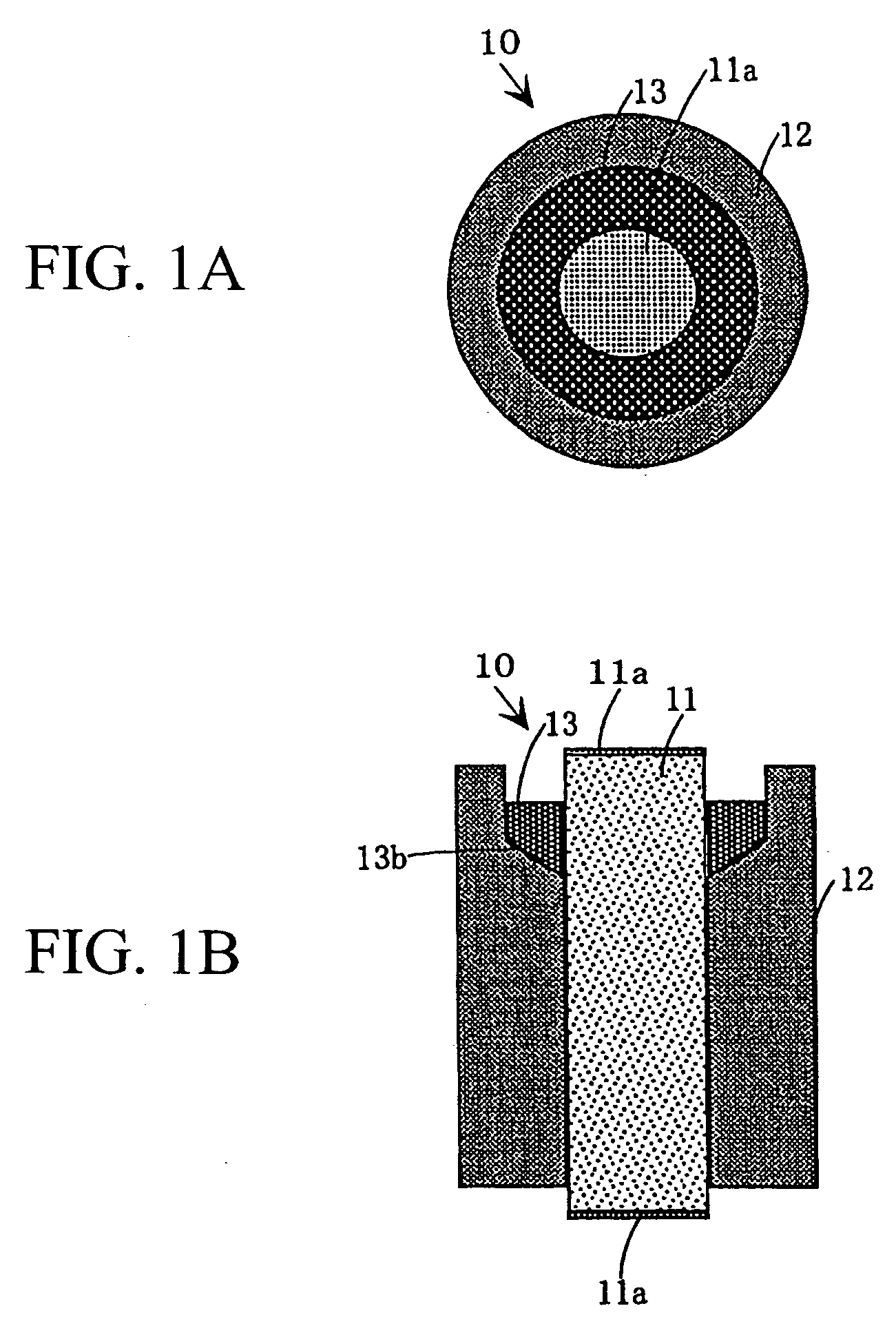
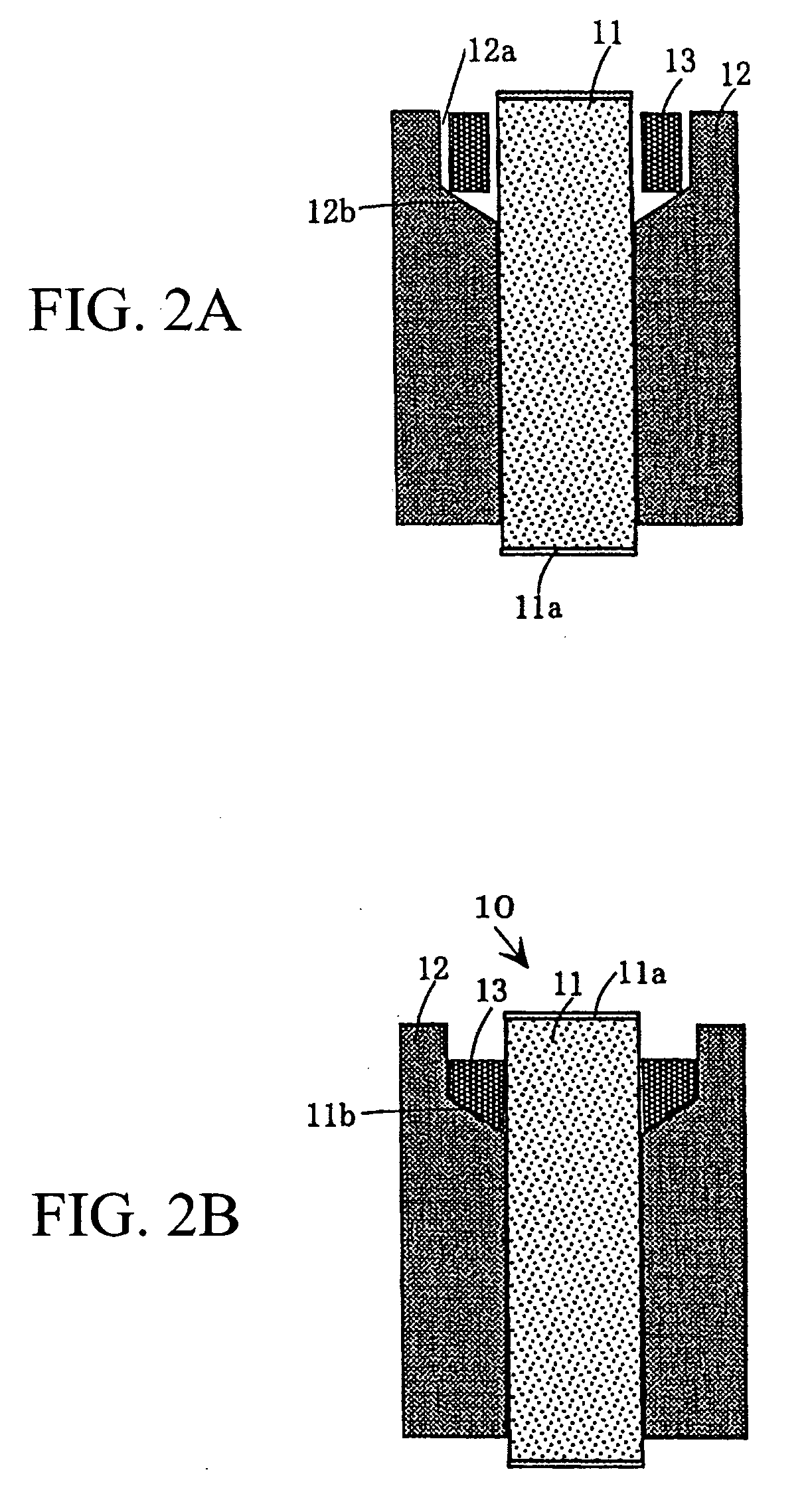
[0039] An optical component in which an optical transmission element, i.e., an optical lens, joins a metal holder will be described with reference to FIGS. 1A, 1B, 2A, and 2B. FIGS. 1A and 1B diagrammatically show an optical component 10 in which an optical lens 11 joins a metal holder 12, wherein FIG. 1A is an upper view of the optical component 10; and FIG. 1B is a cross-sectional view showing the internal structure of the optical component 10 being cut at a plane vertically passing through the center of the illustration of FIG. 1A. FIGS. 2A and 2B show the manner in which the optical lens 11 joins the metal holder 12, wherein FIG. 2A is a cross-sectional view of the optical device 10 before the optical lens 11 completely joins the metal holder 12; and FIG. 2B is a cross-sectional view of the optical device 10 after the optical lens 11 completely joins the meta...


PUM


Abstract

An optical component comprises an optical transmission element (e.g., an optical lens) whose circumferential wall partially joins a metal holder via a joining material (e.g., a low melting point glass), wherein stress is normally applied to the optical transmission element in a compression direction when joining the metal holder. The optical transmission element is inserted into a through hole of the metal holder, and the joining material is kept in a bank actualized by a tapered portion formed in proximity to one end of the through hole of the metal holder. This prevents tensile stress from being applied to the optical transmission element; thus, it is possible to avoid the occurrence of cracks and separations in the optical transmission element; and it is possible to avoid the occurrence of errors in optical characteristics, regardless of variations of the environmental temperature, so that, the optical component is improved in reliability.

Description

BACKGROUND OF THE INVENTION [0001] 1. Field of the Invention [0002] This invention relates to optical components, in which circumferential walls of optical transmission elements such as lenses partially join metal holders via joining materials, and metal holders for holding optical transmission elements. [0003] This application claims priority on Japanese Patent Application No. 2003-328452, the content of which is incorporated herein by reference. [0004] 2. Description of the Related Art [0005] Conventionally, optical devices (or optical components) are designed such that optical transmission elements such as lenses join metal holders via low melting point glasses. FIG. 5 shows an example of the aforementioned optical device, which is disclosed in Japanese Patent Application Publication No. H02-281201. An optical device 40 shown in FIG. 5 is produced using an optical transmission element 41 made of an optical lens having a thermal expansion coefficient of 120×10−7 / ° C., which is arr...

Claims


Application Information

Patent Timeline
IPC IPC(8): G02B7/00G02B7/02
CPCG02B7/008G02B7/028G02B7/025
Inventor HASHIMOTO, YOSHIHIROMATSUOKA, KENTAKAGI, SHINICHISUZUKI, KATSUNORIHAMANO, TETSUTSUGU
Owner MITSUBISHI ELECTRIC CORP
Why Eureka
Try Eureka