
Process and apparatus for removing volatile substances from highly viscous media

a technology of volatile substances and high viscosity, applied in the direction of lighting and heating apparatus, separation processes, machines/engines, etc., can solve the problems of difficult scaling up for larger production plants, inability to generate turbulent flow with the aid of indentations, etc., and achieve the effect of low thermal load

Inactive Publication Date: 2005-05-05
BAYER TECH SERVICES GMBH
View PDF99 Cites 20 Cited by
  • Summary
  • Abstract
  • Description
  • Claims
  • Application Information

AI Technical Summary

Benefits of technology

[0025] These serve as means for increasing the size of the phase boundary between, for example, polymer to be devolatilized and the gas space, in order to accelerate vapor expulsion processes.
[0060] Fundamental investigations have shown that as low a thermal load as possible is required for gentle devolatilization of polymer melts, i.e. a long residence time at low temperature or a short residence time at high temperature and at the same time a narrow residence time distribution. For reasons relating to cost-efficiency, the latter is preferable. Experimental investigations into the evaporator apparatus according to the invention led to the result that these requirements are outstandingly fulfilled by such apparatuses and hence considerable savings in the capital costs of the plant are to be expected.

Problems solved by technology

However, the generation of turbulent flow with the aid of indentations, etc. does not work in the case of the highly viscous polymer melts exhibiting laminar flow.
However, this design is disadvantageous when the side walls of the heat exchanger jacket are connected to the joined tubes.
A disadvantage of this arrangement is that many “dead spaces” exist between the intersecting tubes, in which dead spaces the medium to be heated or to be cooled collects and undergoes thermal decomposition.
Moreover, this design is very complicated and difficult to scale up for larger production plants.
A disadvantage of all designs mentioned is the complicated production of the tubes, at least one shaping and one joining process being necessary.
Moreover, it is intended to dispense with the joint seam, which can lead to disadvantageous changes in the melt flow.

Method used


Image

  • Process and apparatus for removing volatile substances from highly viscous media
  • Process and apparatus for removing volatile substances from highly viscous media
  • Process and apparatus for removing volatile substances from highly viscous media

Examples


example

Removal of Volatile Components from a Polymer Solution:

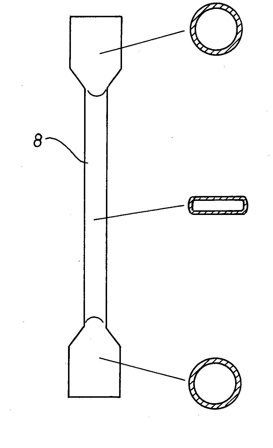
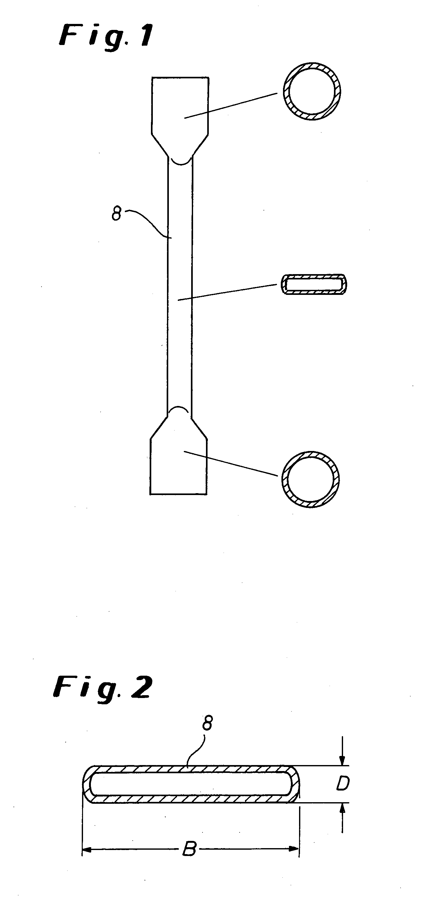
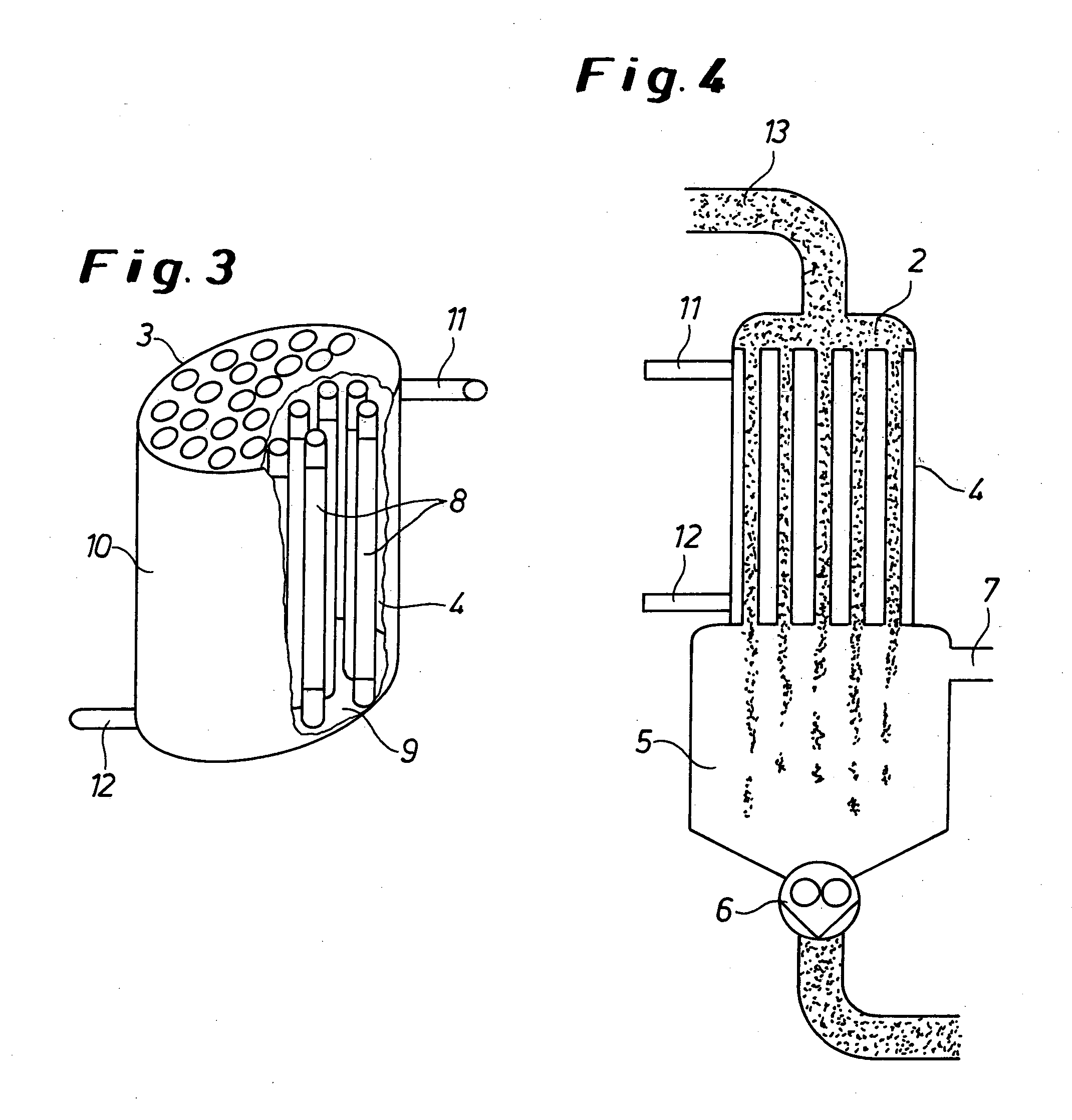
[0082] A preheated polymer solution consisting of about 80% wt. ABS and about 20% wt. of monomer or solvent (acrylonitrile, styrene, ethylbenzene and methyl ethyl ketone) is transported via the feed chamber 2 with perforated tray 3 into a compact-tube heat exchanger having four tubes 8. The tubes have a total length of 1,310 mm, the flat tube region being 1,170 mm long and, in the rectangular region, having a slot thickness D of 3 mm and a slot width B of 12 mm (cf. FIG. 1). The tube 8 is heated with oil by the countercurrent method. The entry temperature of the polymer solution in the heat exchanger 4 is 195° C. The polymer solution flows with a polymer throughput of 6 kg / h downwards through the tubes 8 heated at 240° C. and leaves the tube 8 at a temperature of 226° C. A pressure drop of 52,800 hPa is established over the tube length. The volatile substances are separated from the melt in the devolatilization container 5 at ...


PUM

PropertyMeasurementUnit
heightaaaaaaaaaa
heightaaaaaaaaaa
widthaaaaaaaaaa

Abstract

Evaporator apparatus (1) for the treatment of viscous media comprised of at least a feed chamber (2) having a perforated tray (3), a tube-bundle heat exchanger (4) connected thereto having perpendicularly arranged tubes (8) and a devolatilization chamber (5) connected thereto, a discharge unit (6) for the product and a vapor take-off (7) for removing volatile components, the tubes (8) of the heat exchanger (4) having a rectangular cross section over the greater part of their length.

Description

[0001] The invention relates to a continuous process for particularly gentle heating or concentration of polymer solutions or polymer melts, in particular of thermoplastic polymers, using a tube-bundle heat exchanger comprising compact tubes having flat channels and a cross section variable over the length and a downstream separator, and to an apparatus for carrying out this process. BACKGROUND OF THE INVENTION [0002] The tube-bundle heat exchangers described in industry are used for heating or cooling fluids and for vaporizing volatile substances from viscous media. They usually consist of tubes through which the medium to be devolatilized or to be heated flows and around the outside of which a heating medium flows. The apparatuses are referred to, for example, as flat-tube heat exchangers, falling-tube evaporators or flat-tube evaporators. Fields of use of tube-bundle heat exchangers are, for example, evaporators for polymer solutions, air conditioning systems or refrigerators. [0...

Claims


Application Information

Patent Timeline
Patent Type & Authority Applications(United States)
IPC IPC(8): B01D1/06C08F6/00F28D7/16F28F1/00F28F1/02F28F13/08
CPCB01D1/06C08F6/00F28F13/08F28F1/006F28F1/025F28D7/1684C08F2/01C08F6/10F28F1/00
Inventor KOHLGRUBER, KLEMENS
Owner BAYER TECH SERVICES GMBH
Learn More