
Portable gas fractionalization system

a gas fractionalization and portable technology, applied in auxillary pretreatment, separation processes, instruments, etc., can solve the problems of reducing compressor noise, heavy and cumbersome, and inability to leave home, so as to reduce the thermal load of the psa valve and reduce the noise of the compressor

Inactive Publication Date: 2011-04-12
INOGEN INC
View PDF174 Cites 52 Cited by
  • Summary
  • Abstract
  • Description
  • Claims
  • Application Information

AI Technical Summary

Benefits of technology

[0008]In one aspect, the preferred embodiments of the present invention provide a portable gas fractionalization apparatus comprising a PSA unit having plural adsorbent beds which produce oxygen having a purity of at least 87% and a compressor connected to supply compressed air to the PSA unit. The PSA unit comprises valves operating in accordance with a PSA cycle that, in one implementation, includes a pressure equalization step so as to provide greater than about 31% recovery of oxygen from air. Preferably, the valves of the PSA unit are disposed upstream of the air stream across the compressor such that thermal load on the PSA valves is reduced. Preferably, the compressor is a free piston linear compressor so as to reduce compressor noise. In one embodiment, the compressor is configured to draw ambient air at a flow rate of no more than about 15 slpm. In another embodiment, the free piston linear compressor comprises dual opposing pistons. Preferably, the free piston linear compressor comprises a piston and a sleeve, wherein the piston does not contact the sleeve during operation of the compressor. Preferably, the compressor utilizes a gas bearing system.
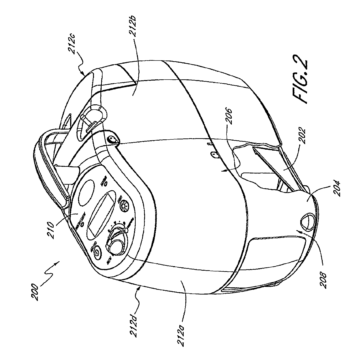
[0010]In one embodiment, the apparatus further comprises a blower which is configured to draw ambient air through the air inlet to provide cooling for the components. Preferably, the housing comprises a circuitous air flow passageway for the ambient air to flow through, wherein the circuitous passageway extends between the air inlet and the air outlet and is configured to reduce noise due to air flow. In another embodiment, the compressor is preferably a free piston linear compressor configured to deliver a feed gas at a flow rate of between about 4 to 9 slpm and at a pressure of about 35 psia while generating a noise level of less than about 35 dB external to the compressor. In certain embodiments, the apparatus further comprises a plurality of sound baffles. Moreover, the housing may also comprise a vibration damper to reduce transfer of vibrational energy from the compressor to the housing.

Problems solved by technology

Thus, patients usually cannot leave home for any length of time unless they carry with them additional cylinders, which can be heavy and cumbersome.
Patients who wish to travel often have to make arrangements with medical equipment providers to arrange for an exchange of cylinders at their destination or along the route, the inconvenience of which discourages many from taking extended trips away from home.
While oxygen concentrators are effective at continual production of oxygen, they are typically large electrically powered, stationary units that generate high levels of noise, in the range of 50-55 dB, which presents a constant source of noise pollution.
Moreover, the units are too heavy to be easily transported for ambulatory use as they typically weigh between 35 to 55 lbs.
Patients who use oxygen concentrators are thus tethered to the stationary machines and inhibited in their ability to lead an active life.
While portable oxygen concentrators have been developed to provide patients with greater mobility, the currently commercially available portable concentrators do not necessarily provide patients with the ease of mobility that they desire.
The portable concentrators tend to generate as much noise as the stationary units and thus cannot be used at places such as the theater or library where such noise is prohibited.
Moreover, the present portable concentrators have very short battery life, typically less than one hour, and thus cannot be used continuously for any length of time without an external power source.

Method used


Image

  • Portable gas fractionalization system
  • Portable gas fractionalization system
  • Portable gas fractionalization system

Examples


Embodiment Construction

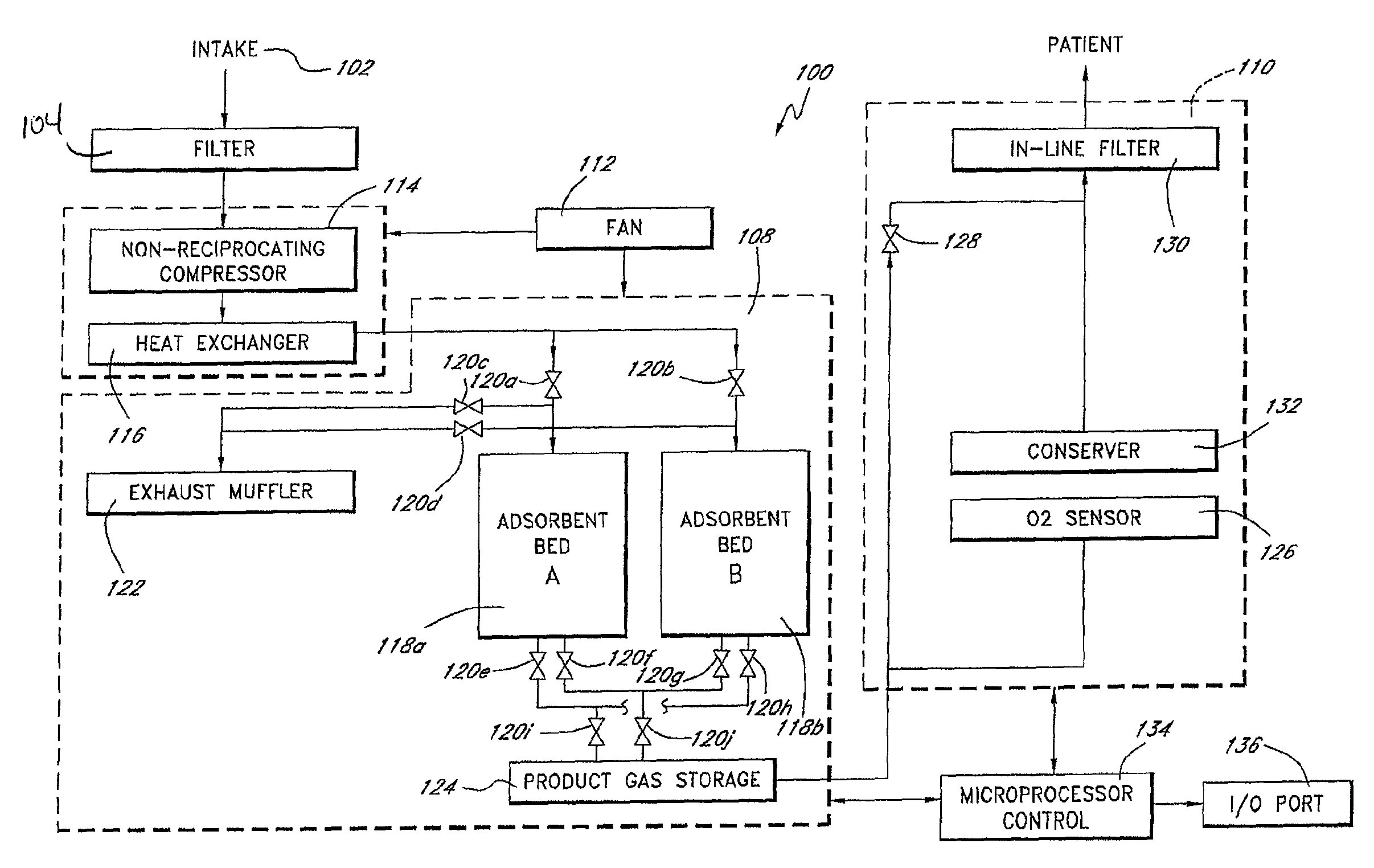
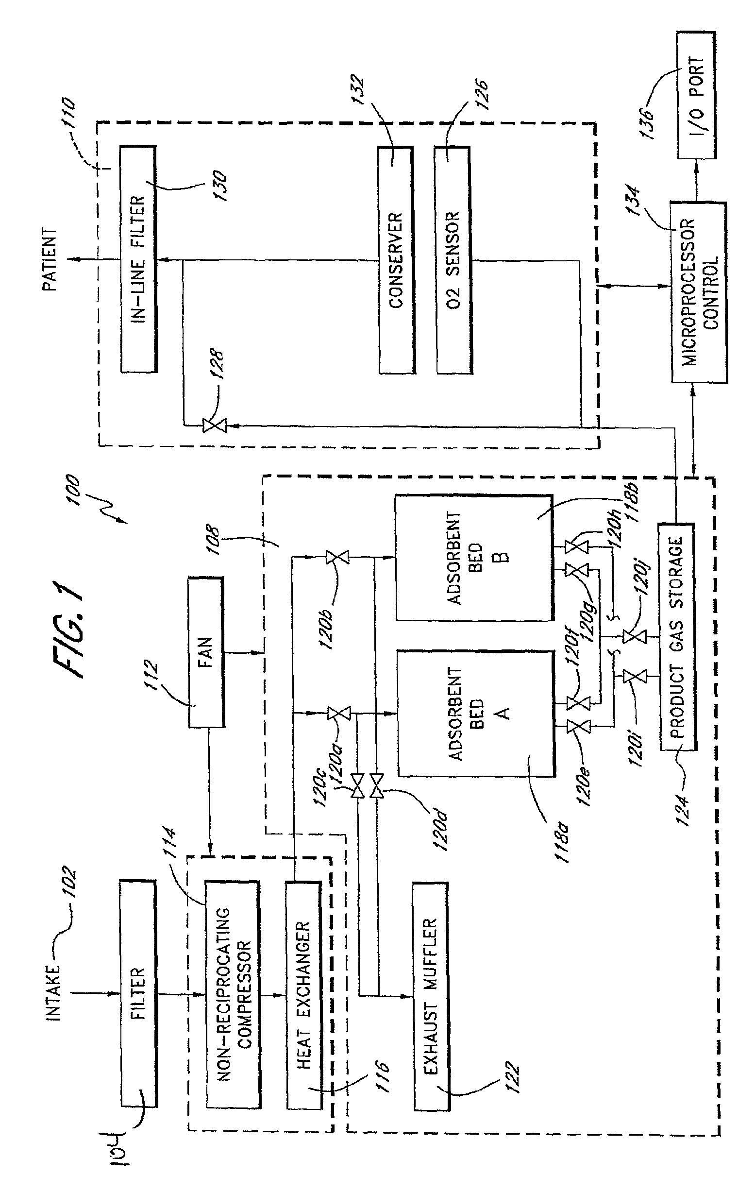
[0035]FIG. 1 schematically illustrates a portable gas fractionalization system 100 of one preferred embodiment of the present invention. As shown in FIG. 1, the system 100 generally comprises an intake 102 through which ambient air is drawn into the system, a filter 104 for removing particulate from the intake air, a compressor assembly 106 for pressurizing the intake air to provide a feed gas, a pressure swing adsorption (PSA) unit 108 which receives and processes the feed gas to produce a product gas having a higher oxygen content than the ambient air, and a gas delivery system 110 for delivering the product gas to a patient.

[0036]Ambient air is drawn through the intake 102 at a relatively low flow rate, preferably no greater than about 15 standard liters per minute (slpm), so as to reduce noise due to airflow through the system. The system 100 further includes a fan 112 that produces an air stream across the compressor assembly 106 also preferably at a relatively low flow rate so...


PUM

PropertyMeasurementUnit
weightaaaaaaaaaa
diameteraaaaaaaaaa
diameteraaaaaaaaaa

Abstract

A portable gas fractionalization apparatus that provides oxygen rich air to patients is provided. The apparatus is compact, lightweight, and low-noise. The components are assembled in a housing that is divided into two compartments. One compartment is maintained at a lower temperature than the other compartment. The lower temperature compartment is configured for mounting components that can be damaged by heat. The higher temperature compartment is configured for mounting heat generating components. An air stream is directed to flow from an ambient air inlet to an air outlet constantly so that there is always a fresh source of cooling air. The apparatus utilizes a PSA unit to produce an oxygen enriched product. The PSA unit incorporates a novel compressor system which includes the use of free piston linear compressors so as to reduce power consumption, noise and vibration reduction.

Description

CROSS-REFERENCE TO RELATED APPLICATIONS[0001]This application is a continuation-in-part of U.S. patent application Ser. No. 10 / 680,885, filed Oct. 7, 2003. This application also claims the benefit of priority under 35 U.S.C. §119(e) of U.S. Provisional Application No. 60 / 775,243 filed on Feb. 21, 2006, which is incorporated herein by reference in its entirety.BACKGROUND OF THE INVENTION[0002]1. Field of the Invention[0003]This invention relates generally to a portable gas fractionalization system, more particularly, to a compact oxygen concentrator that is suitable for both in-home and ambulatory use so as to provide users greater ease of mobility.[0004]2. Description of the Related Art[0005]Patients who suffer from respiratory ailments such as Chronic Obstructive Pulmonary Diseases (COPD) often require prescribed doses of supplemental oxygen to increase the oxygen level in their blood. Supplemental oxygen is commonly supplied to the patients in metal cylinders containing compressed...

Claims


Application Information

Patent Timeline
Patent Type & Authority Patents(United States)
IPC IPC(8): F24J3/00A62B7/00A62B7/10B01D53/02B01D53/30B01D59/26B01D49/00A61M16/10B01D53/04B01D53/047
CPCB01D53/0407B01D53/047A61M16/101A61M2205/8206A61M2209/084B01D2256/12B01D2257/102B01D2259/402B01D2259/4533B01D2253/108A61M2016/1025A61M2202/0208A61M2202/03A61M16/107A61M2202/0007
Inventor DEANE, GEOFFREY FRANKTAYLOR, BRENTON ALAN
Owner INOGEN INC
Learn More