Apparatus for fabricating coating and method of fabricating the coating
- Summary
- Abstract
- Description
- Claims
- Application Information
AI Technical Summary
Benefits of technology
Problems solved by technology
Method used
Image
Examples
first embodiment
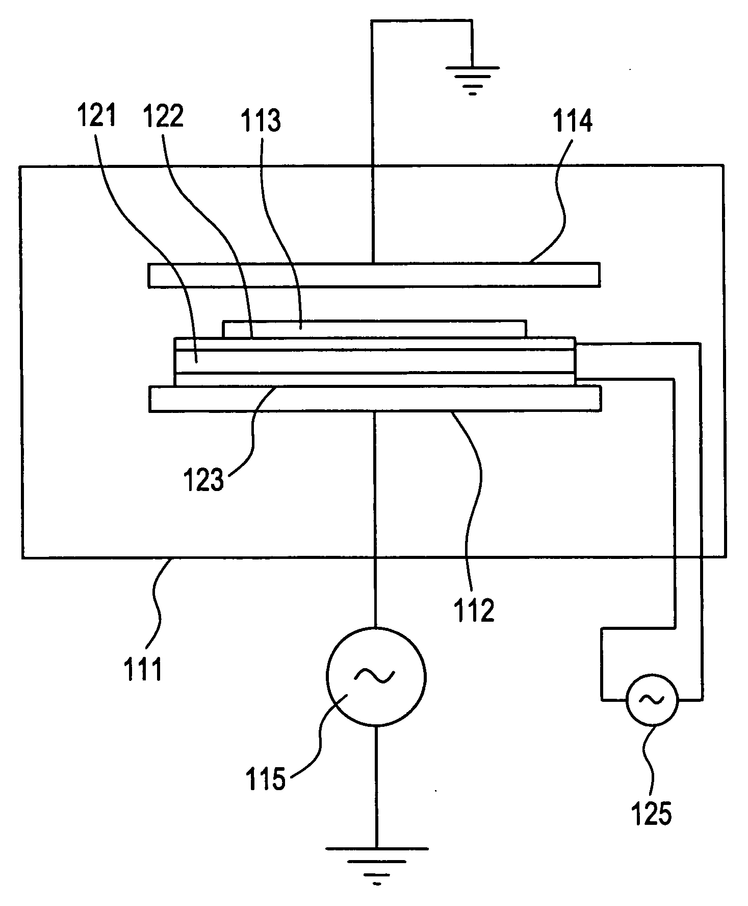
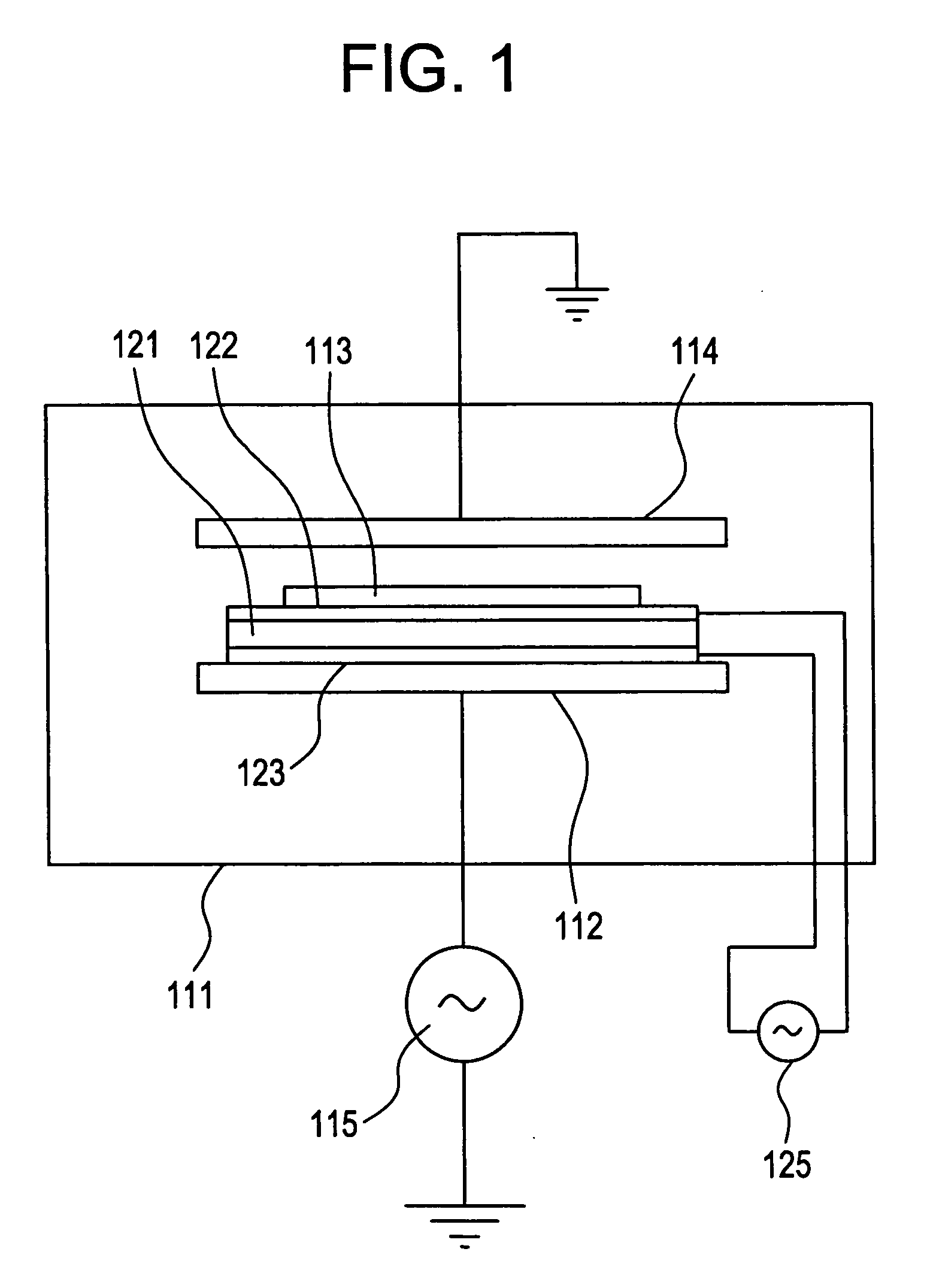
[0085]FIG. 1 is a diagram showing a structure of a plasma CVD apparatus for fabricating a hard carbon coating on a surface of formation while the object 113 is ultrasonic-z,999
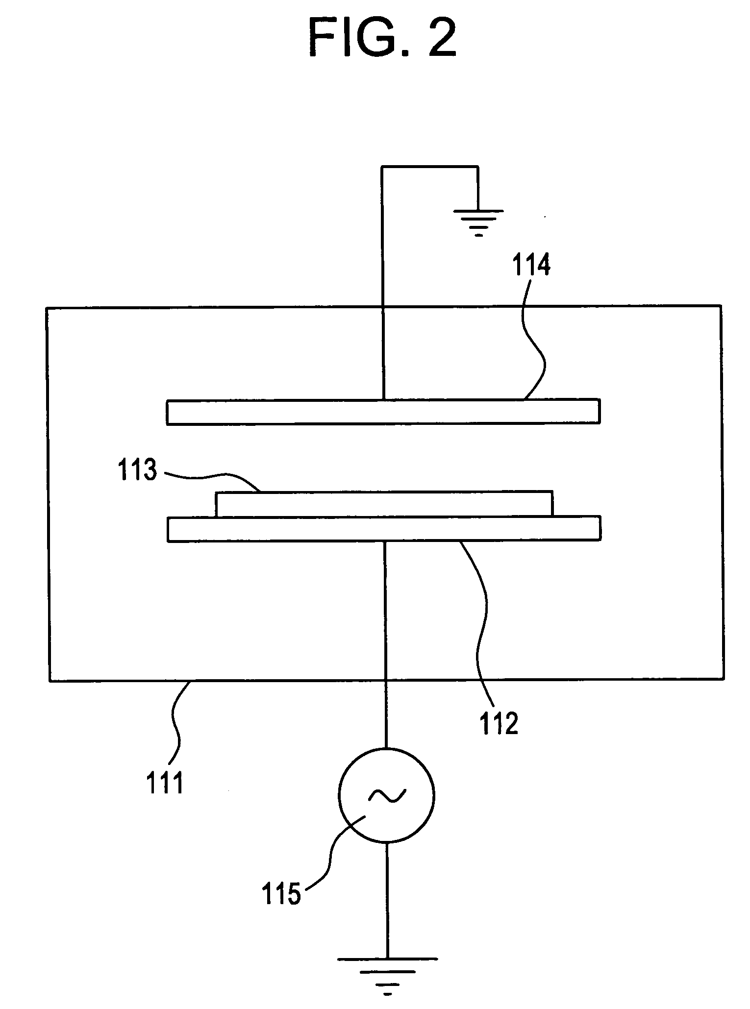
[0086] The plasma CVD apparatus includes a pair of electrodes 112 and 114 for activating reactive gas (producing plasma) within a vacuum vessel 111. An electrode 114 is grounded, and an electrode 112 is connected to a high-frequency power supply 115, which generates, for example, a high-frequency voltage of 13.56 MHz. In the embodiments according to the present invention, in stead of the high frequency power supply 115, an electromagnetic energy suply for supplying electromagnetic energy can be arranged in the apparatus. In this case, DC, AC (50 Hz to 500 KHz) power supply can be used. Although not shown, a matching unit and the like are disposed therein, and in case of need, a heating device using a heater or an infrared light lamp is provided.
[0087] A piezoelectric element 121 interposed between a pair of e...
second embodiment
[0099] In this embodiment, ultrasonic vibrations are given to the object 113 by a method different from that of the first embodiment. FIG. 4 is a diagram showing a structure of a plasma CVD apparatus in accordance with another embodiment of the present invention. As is apparent from FIG. 4, the electrode 112 is vibrated by a ultrasonic vibrator 141 so that the object 113 is ultrasonic-vibrated. Further, with such a structure, the interval between the pair of electrodes 112 and 114 can be set to 10 mm or less to thereby realize high-speed film formation.
third embodiment
[0100]FIG. 5 is a diagram showing a structure of a plasma CVD apparatus for forming a hard carbon coating on a tape-shaped material such as a magnetic tape. The plasma CVD apparatus shown in FIG. 5 includes a vacuum vessel 111, a roll-shaped electrode 155, an electrode 156 paired with the electrode 155, guide rollers 153 and 154 which also act as ultrasonic vibrators, a take-out drum 151 or 152, and a wind-up drum 152 or 151. Although not shown, a gas introducing system and a gas exhausting system for reactive gas, doping gas as well as dilution gas or the like are also provided in the apparatus.
[0101] As the tape-shaped object, a band-shaped object formed of a polyimide film is used. The band-shaped film object 157 travels from one drum 151 or 152 to the other drum 152 or 151 while it is taken up. The drum-shaped electrode 155 is connected to a high-frequency power supply 115 of 13.56 MHz so that discharge is generated between the electrode 155 and the electrode 156 which is a gro...
PUM
| Property | Measurement | Unit |
|---|---|---|
| Length | aaaaa | aaaaa |
| Pressure | aaaaa | aaaaa |
| Pressure | aaaaa | aaaaa |
Abstract
Description
Claims
Application Information
 - R&D
- Intellectual Property
- Life Sciences
- Materials
- Tech Scout
- Unparalleled Data Quality
- Higher Quality Content
- 60% Fewer Hallucinations
Browse by: Latest US Patents, China's latest patents, Technical Efficacy Thesaurus, Application Domain, Technology Topic, Popular Technical Reports.
© 2025 PatSnap. All rights reserved.Legal|Privacy policy|Modern Slavery Act Transparency Statement|Sitemap|About US| Contact US: help@patsnap.com


