Tissue site markers for in vivo imaging

a tissue site marker and in vivo imaging technology, applied in the field of tissue site markers for in vivo imaging, can solve the problems of radiographically visible tissue features, follow-up treatments being misdirected to an undesired portion of the patient's tissue, and may be removed, altered or obscured, etc., to achieve accurate fixation and high reflectivity of incident us energy

Inactive Publication Date: 2005-03-24
SENORX
View PDF70 Cites 69 Cited by
  • Summary
  • Abstract
  • Description
  • Claims
  • Application Information

AI Technical Summary

Benefits of technology

[0026] In addition, for convenience in applying the marker to the tissue site, the specific marker dimensions and shape may be selected so as to accommodate the dimensions of a particular known or novel biopsy needle device or sampling apparatus, while still achieving a distinct and recognizable marker image under medical imaging as placed at the tissue site. By selecting a marker size and shape to fit within the internal diameter of a biopsy needle or sampling device, the marker may be implanted or applied to the biopsy cavity during the course of the biopsy procedure, following sample recovery but prior to removal of the biopsy device. For example, the marker of the invention may have a size and shape selected to permit application of the marker through the hollow interior space of a vacuum assisted large core biopsy device, such as is commercially available from Johnson and Johnson, Ethicon Endosurgery Division. The small physical size of the markers of the invention relative to their acoustic reflectivity permits fitting the markers to a wide variety of biopsy devices.
[0027] In terms of the size of features, including external or in

Problems solved by technology

However, radiographically visible tissue features, originally observed in a mammogram, may be removed, altered or obscured by the biopsy procedure.
This, in turn, can result in follow-up treatments being misdirected to an undesired portion of the patient's tissue.
Such a marke

Method used


Image

  • Tissue site markers for in vivo imaging
  • Tissue site markers for in vivo imaging
  • Tissue site markers for in vivo imaging

Examples


Embodiment Construction

[0045] The following detailed description, and the accompanying drawings to which it refers are provided for purposes of exemplifying and illustrating representative examples and embodiments of the invention only, and are not intended to limit the scope of the invention in any way, and do not exhaustively illustrate and describe all possible embodiments and configurations in which one or more features of the present invention may take physical form.

[0046] All patents and patent applications cited in this specification are herein incorporated by reference as if each individual patent or patent application were specifically and individually indicated to be incorporated by reference.

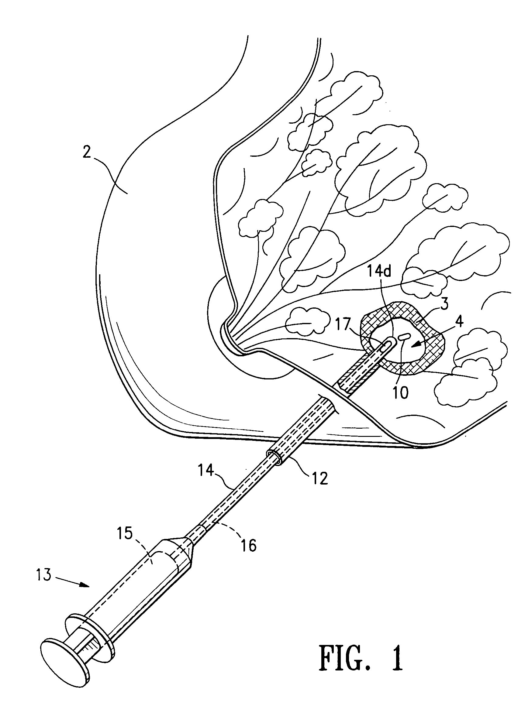
[0047]FIG. 1 shows the use and insertion into a biopsy site of any one of the biopsy site marker embodiments of the invention described herein. FIG. 1 is a perspective view of a human breast 2 having a lesion 3 from which a biopsy specimen has been removed, thereby forming a biopsy cavity 4 within the les...


PUM


Abstract

The invention is directed biopsy site markers and methods of marking a biopsy site, so that the location of the biopsy cavity is readily visible by conventional imaging methods, particularly by ultrasonic imaging. The biopsy site markers of the invention have high ultrasound reflectivity, presenting a substantial acoustic signature from a small marker, so as to avoid obscuring diagnostic tissue features in subsequent imaging studies, and can be readily distinguished from biological features. The several disclosed embodiments of the biopsy site marker of the invention have a high contrast of acoustic impedance as placed in a tissue site, so as to efficiently reflect and scatter ultrasonic energy, and preferably include gas-filled internal pores. The markers may have a non-uniform surface contour to enhance the acoustic signature. The markers have a characteristic form which is recognizably artificial during medical imaging. The biopsy site marker may be accurately fixed to the biopsy site so as to resist migration from the biopsy cavity when a placement instrument is withdrawn, and when the marked tissue is subsequently moved or manipulated.

Description

RELATED APPLICATIONS [0001] The present application is a Continuation-In-Part of U.S. patent application Ser. No. 09 / 241,936, filed Feb. 2, 1999, and a Continuation-In-Part of U.S. patent application Ser. No. 09 / 343,975, filed Jun. 30, 1999. Each of the above referenced patent applications is incorporated by reference herein and the benefit of the filing date of each application is hereby claimed under 35 U.S.C. § 1.20.BACKGROUND OF THE INVENTION [0002] In diagnosing and treating certain medical conditions, it is often desirable to perform a biopsy, in which a specimen or sample of the suspicious tissue is removed for pathological examination, tests and analysis. As is known, obtaining a tissue sample by biopsy and the subsequent examination are typically employed in the diagnosis of cancers and other malignant tumors, or to confirm that a suspected lesion or tumor is not malignant. The information obtained from these diagnostic tests and / or examinations is frequently used to devise...

Claims


Application Information

Patent Timeline
IPC IPC(8): A61B6/00A61B6/12A61B8/08A61B10/00A61B10/02A61B17/00A61B19/00A61K49/00A61K49/04A61K49/22
CPCA61B6/12A61B8/0833A61B10/02A61B19/54A61B2017/00004A61M37/0069A61B2019/5408A61B2019/5425A61B2019/5487A61K49/006A61K49/222A61B2019/481A61B90/39A61B2090/08021A61B2090/3908A61B2090/3925A61B2090/3987
Inventor BURBANK, FRED H.LUBOCK, PAULJONES, MICHAEL L.QUICK, RICHARD L.LOUW, FRANKDE SANTIS, STEPHEN A.
Owner SENORX
Why Eureka
Try Eureka