Temperature measuring system, heating device using it and production method for semiconductor wafer, heat ray insulating translucent member, visible light reflection membner, exposure system-use reflection mirror and exposure system, and semiconductor device produced by using them and vetical heat treating device

Inactive Publication Date: 2005-03-24
SHIN-ETSU HANDOTAI CO LTD
View PDF15 Cites 185 Cited by
  • Summary
  • Abstract
  • Description
  • Claims
  • Application Information

AI Technical Summary

Benefits of technology

In this temperature measurement system, temperature is measured by disposing the reflecting member so as to oppose with a temperature measurement surface of the object-to-be-measured while forming a reflection gap between itself and the temperature measurement surface, extracting heat ray through the heat ray extraction pathway section penetrating the reflecting member, and detecting the heat ray with the temperature detection section composed of a radiation thermometer, for example. The purpose of adopting such configuration is to allow multiple reflection of the heat ray between the temperature measurement surface and reflecting member so as to enhance effective radiation ratio of the temperature measurement surface, and so as to relieve an influence of difference in real radiation ratio among the individual objects-to-be-measured or an influence of variation in the radiation ratio of a single object-to-be-measured, to thereby carry out precise temperature measurement. The foregoing paragraphs have already described that it is particularly important to raise the reflectivity of the reflecting member as possible.
As is obvious from FIG. 65, only by simply disposing the heat ray reflecting materials fabricated in Experimental Case 1 in the vicinity of the furnace entrance, temperature in a region outside the original length of uniform heating was raised to as much as several tens of degrees centigrade. In other words, it was found that in-furnace position where the same temperature can be reached was expanded by maximum 50 to 60 mm or around towards the furnace entrance side. This demonstrated that the use of the heat ray reflecting material of the sixth invention was effective in expanding the length of uniform heating of the annealing furnace.

Problems solved by technology

Difference less than 1.1 in refractive index of the adjacent element reflecting layers composing the heat ray reflecting material inevitably lowers the reflectivity, and increase in the number of stacking for the purpose of increasing the reflectivity results in increased costs.

Method used


Image

  • Temperature measuring system, heating device using it and production method for semiconductor wafer, heat ray insulating translucent member, visible light reflection membner, exposure system-use reflection mirror and exposure system, and semiconductor device produced by using them and vetical heat treating device
  • Temperature measuring system, heating device using it and production method for semiconductor wafer, heat ray insulating translucent member, visible light reflection membner, exposure system-use reflection mirror and exposure system, and semiconductor device produced by using them and vetical heat treating device
  • Temperature measuring system, heating device using it and production method for semiconductor wafer, heat ray insulating translucent member, visible light reflection membner, exposure system-use reflection mirror and exposure system, and semiconductor device produced by using them and vetical heat treating device

Examples


Embodiment Construction

Best modes for carrying out the invention will be described below referring to the attached drawings.

(First Invention)

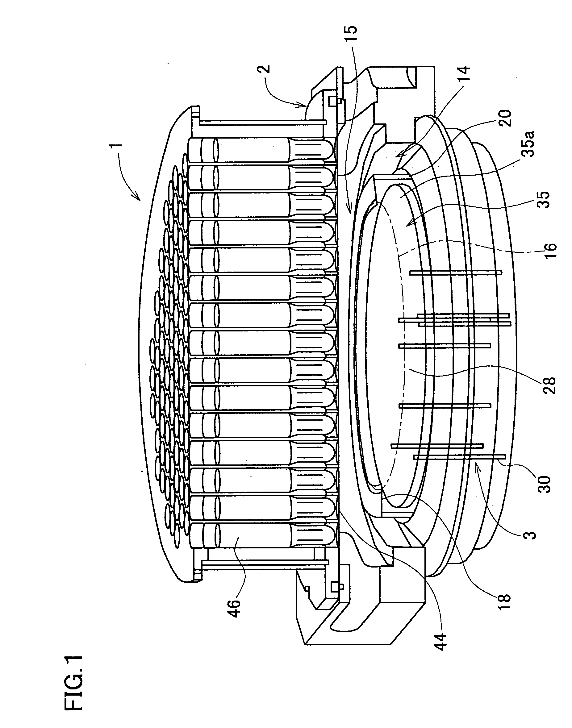
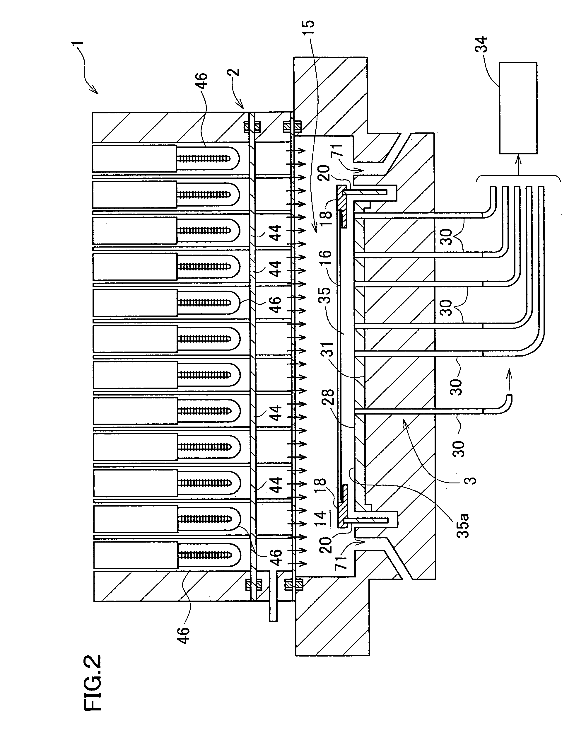
Best modes for carrying out the first invention will be described below referring to the attached drawings, where the first invention is by no means limited thereto. FIG. 1 shows a heating apparatus 1 according to one embodiment of the first invention, and is configured as a heating apparatus for RTP. In the heating apparatus 1, an object-to-be-processed is a silicon single crystal wafer 16, and comprises a container 2 having a housing space 14 for the wafer 16 formed therein; a heating lamp 46 typically configured as a tungsten-halogen lamp for heating the wafer 16 in the housing apace 14, and a temperature measuring system 3 disposed so that a reflecting plate (reflecting member) 28 thereof is opposed to the wafer 16. The inner space of the housing space 14 is evacuated through an exhaust port 71. The reflecting plate 28 is disposed so as to be opposed approxi...


PUM


Abstract

Oppositely of a temperature measuring surface of an object-to-be-measured 16, a reflecting member 28 is disposed while being spaced by a reflection gap 35 from the temperature measuring surface. The reflecting member 28 is composed of a heat ray reflecting material capable of reflecting heat ray in a specific wavelength band, in a portion including a reflection surface 35a. A heat ray extraction pathway section 30 is disposed through the reflecting member 28 so that one end thereof faces the temperature measuring surface. Heat ray extracted through the heat ray extraction pathway section from the reflection gap is detected by a temperature detection section 34. The heat ray reflecting material is configured in a form of a stack comprising a plurality of element reflecting layers composed of a material having transparent properties to the heat ray, in which every adjacent two element reflecting layers are composed of a combination of materials having refractive indices which differ from each other by 1.1 or more. This makes the measurement be hardly affected by radiation ratio of the object-to-be-measured when temperature of the object-to-be-measured is measured by a radiation thermometer, enables to measure its temperature more correctly irrespective of the surface state thereof, and can simplify configuration of a measurement system.

Description

TECHNICAL FIELD In this invention, a first invention relates to a heat ray reflecting material capable of efficiently reflecting heat ray of a specific wavelength band emitted from an exothermic body, and a heating apparatus using the same. A second invention relates to a lamp. A third invention relates to a heat ray intercepting light transmissive member. A fourth invention relates to a visible light reflecting member as a reflecting mirror capable of efficiently reflecting visible light in a specific wavelength region which belongs to the visible light wavelength band. A fifth invention relates to a reflecting mirror for light exposure apparatus, a light exposure apparatus per se, and a semiconductor device fabricated using these, especially relates to a reflecting mirror for light exposure apparatus, a light exposure apparatus per se, and a semiconductor device fabricated using these which are appropriate for exposure light of shorter wavelength in ultraviolet wavelength region ...

Claims


Application Information

Patent Timeline
IPC IPC(8): E06B7/08E06B9/386G01J5/00G01J5/08G02B7/18H01L21/00
CPCE06B9/386E06B2009/2464G01J5/0003G01J5/0007G01J5/08H01L21/67248G01J5/0821G01J5/0846G02B7/181G02B7/1815H01L21/67115G01J5/0809G01J5/0808G01J5/0813
Inventor ABE, TAKAOIMAI, MASAYUKI
Owner SHIN-ETSU HANDOTAI CO LTD
Why Eureka
Try Eureka