
Communication device, communication method and program

a communication method and communication method technology, applied in the field of communication devices, communication methods and programs, can solve the problems of reducing the phy rate, compromising the communication quality, and the quality of post-link adaptation communication remains poorer than the communication quality, so as to reduce the communication quality

Inactive Publication Date: 2010-04-20
SONY CORP
View PDF34 Cites 7 Cited by
  • Summary
  • Abstract
  • Description
  • Claims
  • Application Information

AI Technical Summary

Benefits of technology

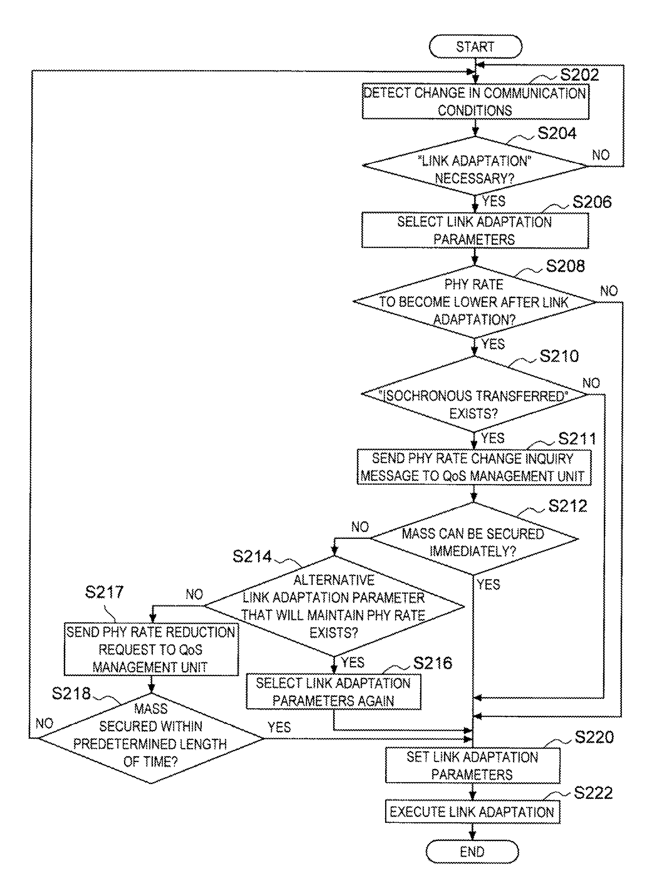
The present invention provides a new and improved communication device, method, and program for executing link adaptation in a communication mode with other communication devices. The device detects communication conditions, makes a decision on whether to execute link adaptation based on those conditions, selects a link adaptation parameter, makes an advance decision on whether the data transfer rate will become lower, decides on the transfer mode (quality assurance mode or not), and executes the link adaptation based on the selected parameters. This method helps to prevent poor communication quality caused by link adaptation and ensures high-quality communication.

Problems solved by technology

However, the base station apparatus adopting the method disclosed in the publication will execute link adaptation even when the desired time slots are difficult to be secured, which may result in a condition under which the PHY rate is lowered.
Under such circumstances, the quality of post-link adaptation communication will remain poorer than the communication quality prior to the link adaptation, until the desired time slots are secured.
For this reason, the link adaptation method, which may greatly, compromise communication quality either temporarily or intermittently, is difficult to be readily adopted in a communication mode in which assurance of high quality communication is important.

Method used


Image

  • Communication device, communication method and program
  • Communication device, communication method and program
  • Communication device, communication method and program

Examples


embodiment

[0059]The following is a detailed explanation of the communication device achieved in the embodiment of the present invention, given in reference to drawings. It is to be noted that the same reference numerals are assigned to identical components so as to preclude the necessity for a repeated explanation thereof.

[0060](Structure of Communication Device 100)

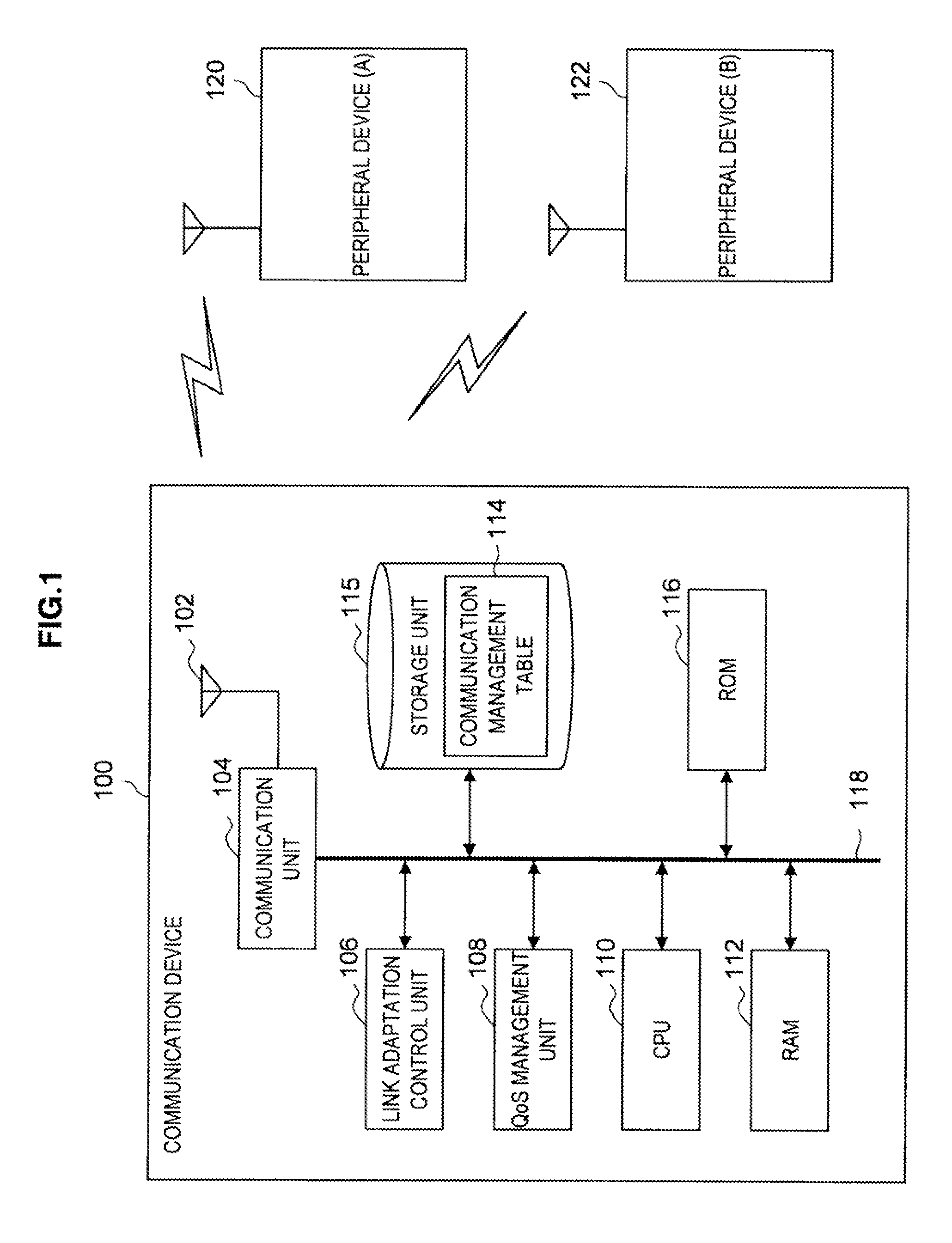
[0061]First, the functional structure of the communication device achieved in the embodiment is explained in reference to FIG. 1. FIG. 1 is a block diagram of the functional structure adopted in the communication device in the embodiment.

[0062]The communication device 100 in the embodiment includes, as its principal components, an antenna 102, a communication unit 104, a QoS management unit 108, a CPU (Central Processing Unit) 110, a RAM (Random Access Memory) 112, a storage unit 115 and a ROM (Read Only Memory) 116. In addition, a communication management table 114 is held in the storage unit 115, which is connected via a bus 118...


PUM


Abstract

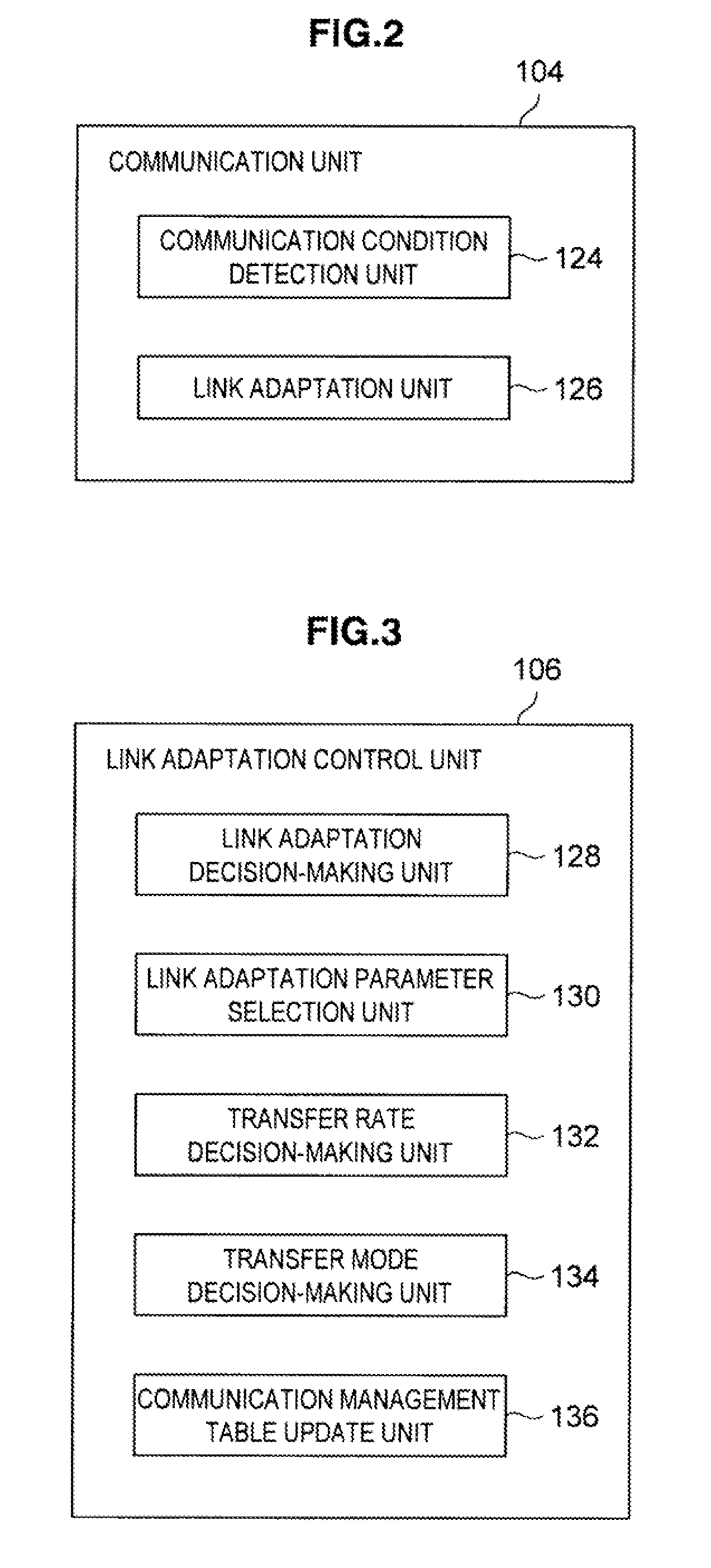
The communication device according to the present invention includes a communication condition detection unit that detects communication conditions with regard to communication with other communication devices, a link adaptation decision-making unit that makes a decision as to whether or not link adaptation needs to be executed in correspondence to the communication conditions, a link adaptation parameter selection unit that selects a link adaptation parameter to be used for the link adaptation when the link adaptation is judged to be necessary, a transfer rate decision-making unit that makes an advance decision as to whether or not the data transfer rate is to become, lower compared to the pre-link adaptation state if the link adaptation is executed based upon the selected link adaptation parameter and a link adaptation unit that executes the link adaptation based upon the selected link adaptation parameter if the data transfer rate is judged not to become lower.

Description

CROSS REFERENCES TO RELATED APPLICATIONS[0001]The present invention contains subject matter related to Japanese Patent Application JP 2006-222096 filed in the Japan Patent Office on Aug. 16, 2006, the entire contents of which are incorporated herein by reference.BACKGROUND OF THE INVENTION[0002]1. Field of the Invention[0003]The present invention relates to a communication device, a communication method and a program.[0004]2. Description of the Related Art[0005]The “link adaptation” technologies have come to be recognized in recent years in the area of wireless communication as effective means for improving the communication state by controlling the communication method in correspondence to the communication conditions under which a plurality of communication devices communicate with one another. A given communication device may execute link adaptation by adjusting the transfer rate (PHY rate) for a physical layer, the packet size, the modulation method or the transmission power as ...

Claims


Application Information

Patent Timeline
Patent Type & Authority Patents(United States)
IPC IPC(8): H04J3/22H04W28/18
CPCH04W28/18
Inventor IHORI, AKIHIRO
Owner SONY CORP
Learn More