
Process for producing a metal layer on a substrate body, and substrate body having a metal layer

a metal layer and substrate technology, applied in the direction of non-resonant long antennas, textiles and papermaking, record information storage, etc., can solve the problems of high consumption of chemicals, large waste of raw materials used (aluminium layer) on account of subtractive process, and low throughput rate. achieve the effect of simple and inexpensive production, high reliability and easy production

Inactive Publication Date: 2005-03-10
INFINEON TECH AG
View PDF10 Cites 14 Cited by
  • Summary
  • Abstract
  • Description
  • Claims
  • Application Information

AI Technical Summary

Benefits of technology

[0009] Therefore, an object of the present invention is to provide a process for producing a metal layer on a substrate body with which it is relatively simple and inexpensive to produce a metal layer with a low electrical resistance on a substrate body. Furthermore, the process is also to allow inexpensive production of structured metal layers.
[0010] A further object of the invention is to describe a substrate body having a metal layer which has a low electrical resistance and is inexpensive to produce.

Problems solved by technology

The process described, which makes use of a subtractive principle, has the drawback that only low throughput rates can be achieved, a high consumption of chemicals is required and large parts of the raw materials used (aluminium layer) are wasted on account of the subtractive process.
Conductive pastes have the drawback of having a high electrical resistance.
Furthermore, they are generally very expensive, since the conductive particles usually consist of silver, and the proportion of silver in the conductive paste is over 90%.
In addition to the high costs, the high thickness of >50 μm of the conductive paste is also worth noting, with the result that the thickness of the structure comprising substrate body and metal layer increases.
It is unlikely that all the unmelted metal powder will drop off the top side under the force of gravity, and consequently further work is required.

Method used


Image

  • Process for producing a metal layer on a substrate body, and substrate body having a metal layer
  • Process for producing a metal layer on a substrate body, and substrate body having a metal layer
  • Process for producing a metal layer on a substrate body, and substrate body having a metal layer

Examples


Embodiment Construction

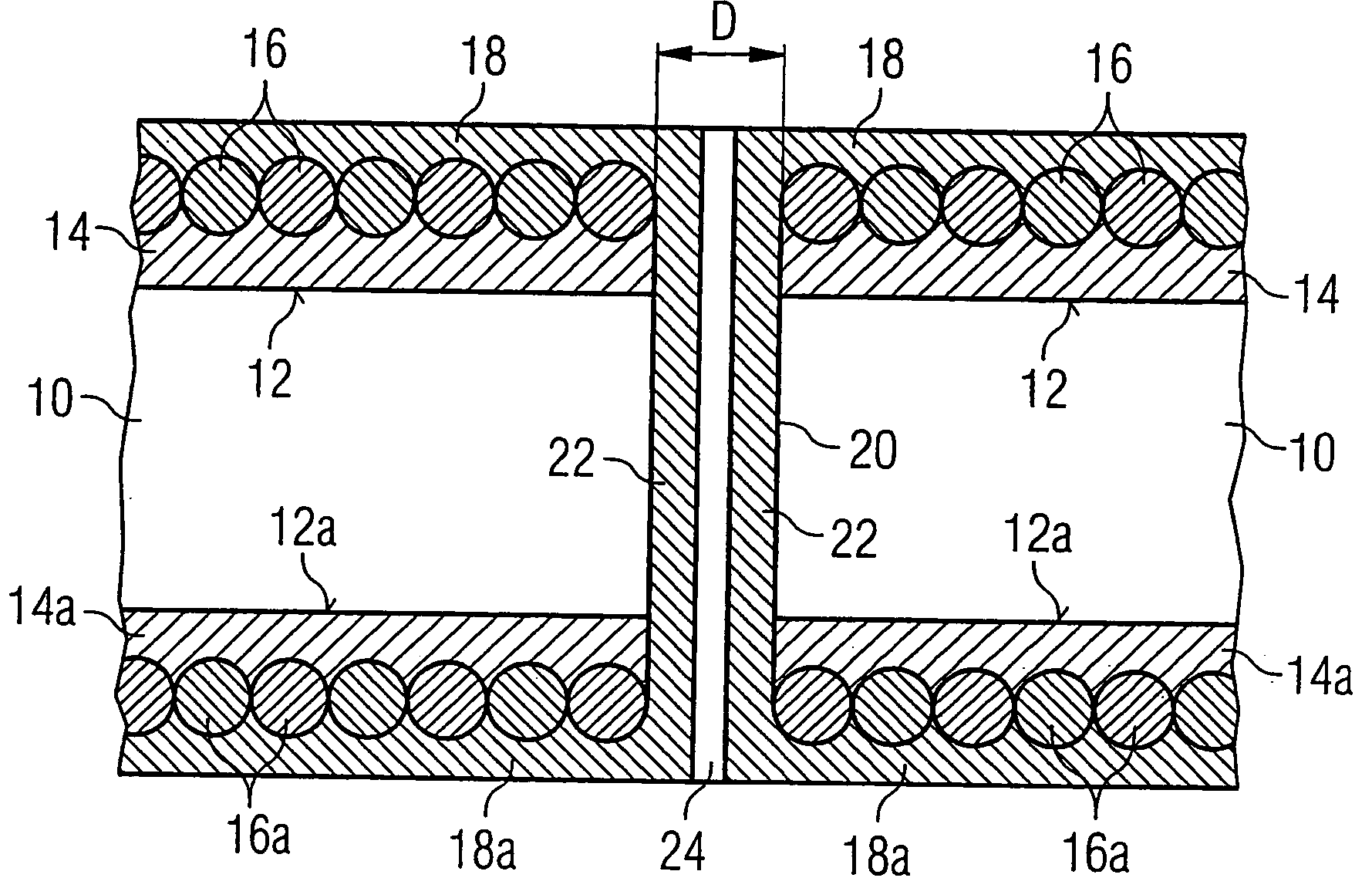
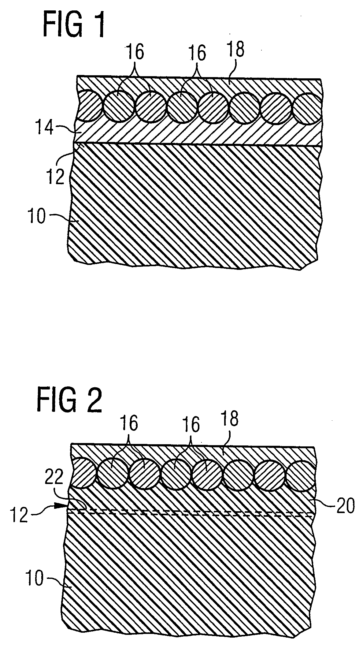
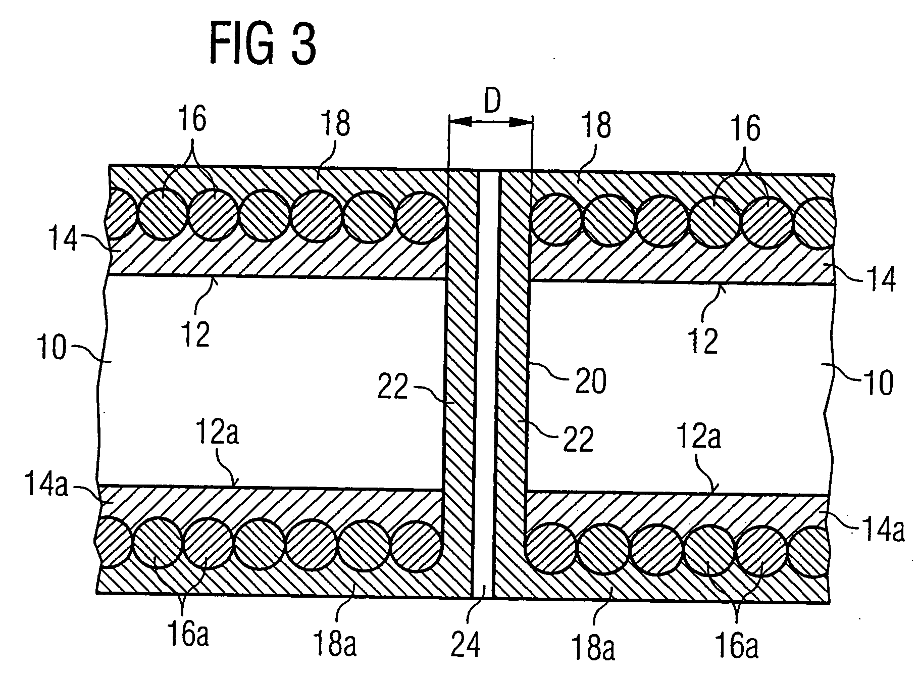
[0045]FIG. 1 shows a sectional illustration of part of a substrate body 10, to the surface 12 of which a bonding layer 14 has been applied in a first process step. In a subsequent, second process step, conductive particles 16 have been applied close together to the optionally structured bonding layer 14. In the present exemplary embodiment, the conductive particles 16 are round in cross section. However, the cross section of the conductive particles could be of any desired form. The conductive particles 16, which consist, for example, of copper, iron, nickel, gold, silver, aluminium, brass or any other desired alloy, are fixed to the bonding layer 14. The conductive particles could also be graphites or polymers which are in powder form and are applied, for example, by being blown, sprayed, rolled or brushed on.

[0046] The conductive particles 16 are fixed to the bonding layer 14 for example as a result of the application of the particles 16 taking place during a phase in which the b...


PUM

PropertyMeasurementUnit
Thicknessaaaaaaaaaa
Pressureaaaaaaaaaa
Adhesion strengthaaaaaaaaaa

Abstract

Process for producing a metal layer on a substrate body. The process includes applying conductive particles to a surface of the substrate body, so that the conductive particles are fixed to the substrate body, and metallizing the substrate body together with the particles chemically and / or by electrodeposition in a metallization bath so as to form the metal layer.

Description

CROSS-REFERENCE TO RELATED APPLICATION [0001] This application is a continuation of International Patent Application Serial No. PCT / DE02 / 03201, filed Aug. 30, 2002, which published in German on Apr. 3, 2003 as WO 03 / 027353, and is incorporated herein by reference in its entirety.FIELD OF THE INVENTION [0002] The invention relates to a process for producing a metal layer on a substrate body, in which the metal layer can be produced either in structured form or over the entire surface. The invention also relates to a substrate body having a structured metal layer or a metal layer over the entire surface. BACKGROUND OF THE INVENTION [0003] Various processes are known from the prior art for production of a metal layer on a substrate body. Many of these proposals deal with the way in which structured metal layers, for example in the form of antenna coils or flat coils, can be produced. The term “structured metallization” is to be understood in the text which follows as meaning all profil...

Claims


Application Information

Patent Timeline
IPC IPC(8): C23C2/02C23C18/16H05K3/10H05K3/24H05K3/38
CPCC23C2/02Y10T428/24893H05K3/246H05K3/386C23C18/1889C23C18/2033C23C18/1865C23C18/1841C23C18/1817C25D5/54C25D5/56C23C18/208C23C18/31Y10T428/24355Y10T428/24917Y10T428/25H05K3/102
Inventor GUNDLACH, HARALDMULLER-HIPPER, ANDREASSIMMERLEIN-ERLBACHER, EWALD
Owner INFINEON TECH AG
Learn More