Scanning probe microscope and scanning method

a scanning probe and microscope technology, applied in the direction of mechanical measurement arrangement, mechanical roughness/irregularity measurement, instruments, etc., can solve the problems of increasing incline slip, bending of the probe and cantilever due to lateral force undergoing from the incline, and difficulty in separating the probe tip from the adhesive water layer with small amplitude, etc., to achieve the effect of improving throughput, reducing incline slip, and reducing incline slip

Active Publication Date: 2005-03-10
HITACHI HIGH TECH SCI CORP
View PDF4 Cites 19 Cited by
  • Summary
  • Abstract
  • Description
  • Claims
  • Application Information

AI Technical Summary

Benefits of technology

[0023] In view of the foregoing circumstances, the present invention has been made. It is an object of the invention to provide a scanning probe microscope and scanning method which can reduce or avoid damage due to collision between a probe tip and a sample, reduce the measuring time, improve the throughput, enhance the measuring accuracy, and collect observational data such as topographic data about a surface of the sample without being affected by an adhesive water layer.

Problems solved by technology

For this reason, it has been difficult to separate the probe tip from the adhesive water layer with small amplitudes.
Therefore, if the vibration amplitude is increased, there is the danger that a collision occurs between the probe and sample, producing a damage.
Furthermore, as described also in Non-Patent Reference 2, if the force with which the incline is tapped is increased, slip occurring on the incline increases.
In addition, bending of the probe and cantilever due to lateral force undergoing from the incline increases.
Therefore, it has been difficult to accurately measure the topography of a steep incline.
This produces the problem that measurements cannot be made precisely.
Furthermore, if the scan rate is increased, the probe cannot follow the topography of the sample surface and thus it is difficult to make measurements precisely.
Consequently, limitations are imposed on the scan rate.
This deteriorates the throughput.
In addition, it takes a long time to make measurements.
Additionally, where the servo gain that is used as a parameter in controlling the distance between the probe and sample is increased, hunting oscillation occurs, making it difficult to perform precise measurements.
Therefore, it takes a long time to perform measurements.
This produces the disadvantage that the throughput is deteriorated.
Especially, since the probe tip is so set that it always returns to the same position (initial position) regardless of the topography of the sample surface, it may take a longer time according to the topography of the sample surface.
In consequence, it also takes a longer time to perform measurements, and the throughput is deteriorated.

Method used


Image

  • Scanning probe microscope and scanning method
  • Scanning probe microscope and scanning method
  • Scanning probe microscope and scanning method

Examples


Embodiment Construction

[0076] A first embodiment of the scanning probe microscope according to the present invention is hereinafter described with reference to FIGS. 1 to 5.

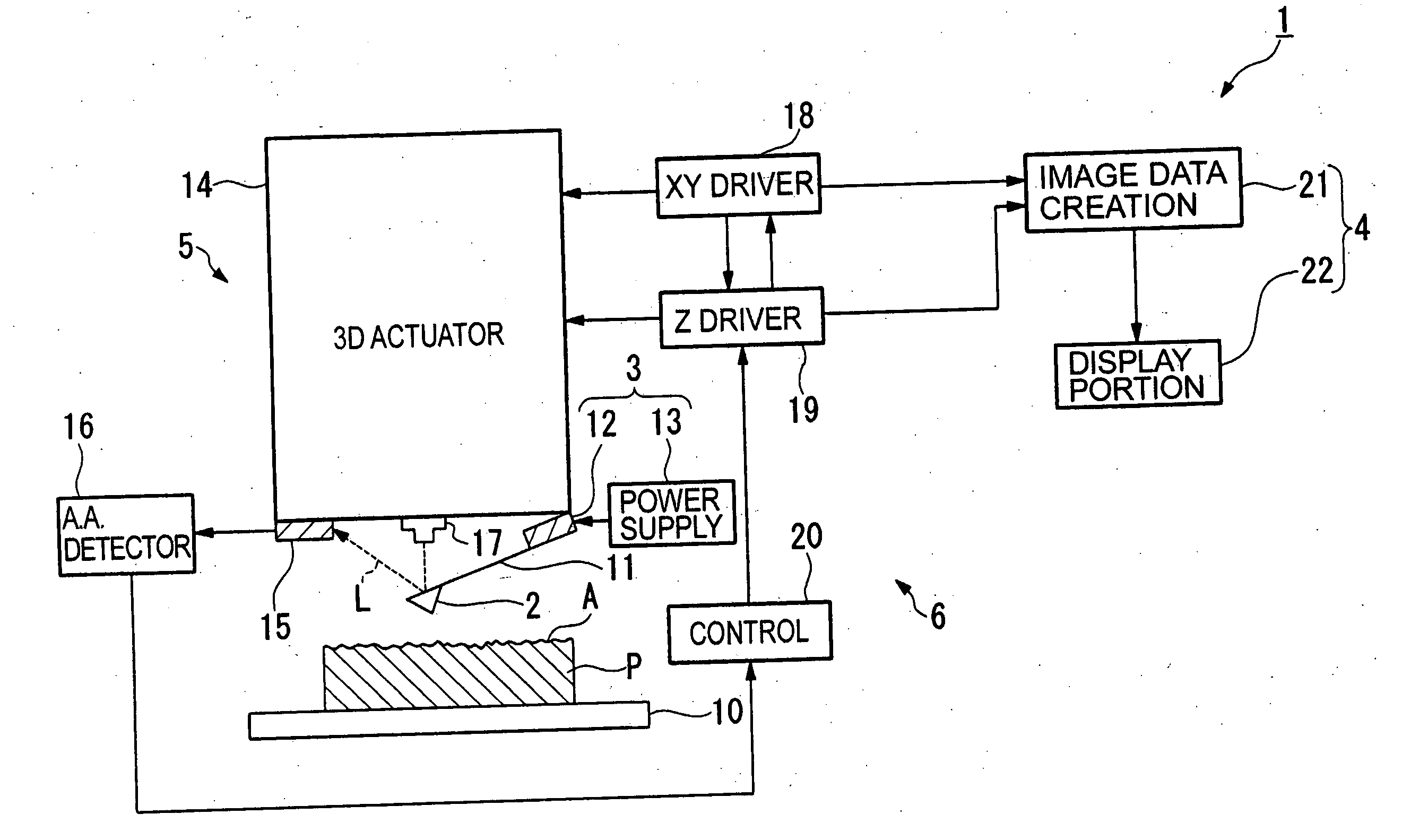
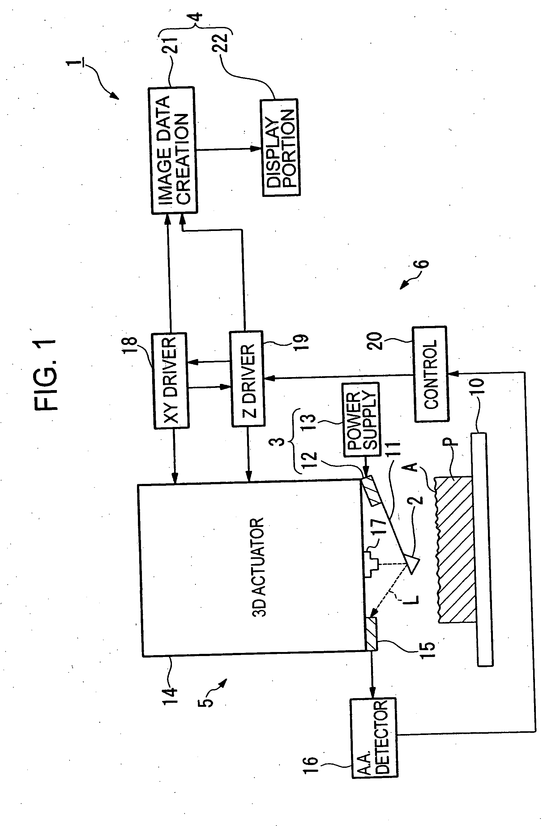
[0077] The scanning probe microscope according to the present invention is generally indicated by reference numeral 1 in FIG. 1 and has a probe tip 2 capable of scanning in X- and Y-directions parallel to a surface (hereinafter referred to as the sample surface A) of a sample P and of moving in the Z-direction vertical to the sample surface A, all relative to the sample surface A, a vibration unit 3 for vibrating the tip 2 at a vibration frequency that resonates with or forcedly vibrates the tip, an observation unit 4 for collecting observational data when the tip 2 is in proximity or contact with the sample surface A, a detection unit 5 for detecting variations in the state of vibration of the tip 2 when the tip 2 is in proximity or contact with the sample surface A, and a control unit 6 for controlling the scans of the tip 2 in the ...


PUM


Abstract

There are disclosed a scanning probe microscope and scanning method capable of reducing or avoiding damage due to collision between a probe tip and a sample, shortening the measuring time, improving the throughput and measuring accuracy, and collecting observational data such as topographic data about the sample surface without being affected by an adhesive water layer. The microscope has a vibration unit for vibrating the probe tip, an observation unit for collecting observational data when the tip is in proximity or contact with the sample surface, a detector for detecting a variation in the state of vibration of the tip when it is in proximity or contact with the sample surface, and a control unit for controlling movement of the tip in X- and Y-directions parallel to the sample surface and in a Z-direction vertical to the sample surface. After collecting the observational data, the control unit scans the tip in a direction parallel to the sample surface until a next observation position in the X- or Y-direction is reached. During the scanning, if a variation in the state of vibration of the tip is detected, the control unit moves the tip in the Z-direction away from the sample surface.

Description

BACKGROUND OF THE INVENTION [0001] 1. Field of the Invention [0002] The present invention relates to a scanning probe microscope and scanning method capable of obtaining information about the surface characteristics such as the surface topography of a sample by scanning a probe tip over a sample surface while vibrating the tip. [0003] 2. Description of the Related Art [0004] As is well known in the art, scanning probe microscopes such as atomic force microscopes and scanning tunneling microscopes are known as instruments for measuring a sample such as an electronic material in a microscopic region and imaging the surface topography of the sample or measuring information about surface characteristics. Various kinds of instruments are offered as this type of scanning probe microscope. One known instrument is an ultra-low force atomic force microscope (AFM) for detecting the surface topography of a sample by scanning a probe tip parallel to a surface of the sample while vibrating the t...

Claims


Application Information

Patent Timeline
IPC IPC(8): G01Q10/00G01Q10/02G01Q10/04G01Q10/06G01Q60/24G01Q60/32
CPCB82Y35/00G01Q60/32G01Q10/065
Inventor KITAJIMA, ITARUWATANABE, KAZUTOSHIWAKIYAMA, SHIGERUYASUTAKE, MASATOSHIINOUE, AKIRA
Owner HITACHI HIGH TECH SCI CORP
Why Eureka
Try Eureka