
Temperature and condensation control system for functional tester

a temperature and condensation control and functional tester technology, applied in the direction of electronic circuit testing, measurement devices, instruments, etc., can solve the problems of affecting the accuracy of affecting the accuracy of test results, so as to reduce the exposure of test equipment and chips, prevent condensation on surfaces, and reduce the effect of condensation

Inactive Publication Date: 2005-02-10
IBM CORP
View PDF8 Cites 12 Cited by
  • Summary
  • Abstract
  • Description
  • Claims
  • Application Information

AI Technical Summary

Problems solved by technology

Such a part may pass tests and reach a customer, but will fail at a higher frequency rate than is acceptable.
Similarly, some chip failure modes are found only at elevated temperatures, while other early use failures which might not have occurred until after reaching a customer may be found during testing at elevated temperatures.
However, testing at varying temperature also raises certain problems.
Clearly, any tester surfaces exposed to this environment and operating at −20 C contains mechanical components with surface temperatures that are well below the dew point and will cause condensation of the water vapor in the air on those surfaces.
Condensed water within the machine could cause electrical shorts, destroying the tester and / or the tested chip or module.
In addition, condensed water escaping from the tester would disrupt manufacturing operations due to safety and related issues.

Method used


Image

  • Temperature and condensation control system for functional tester
  • Temperature and condensation control system for functional tester
  • Temperature and condensation control system for functional tester

Examples


Embodiment Construction

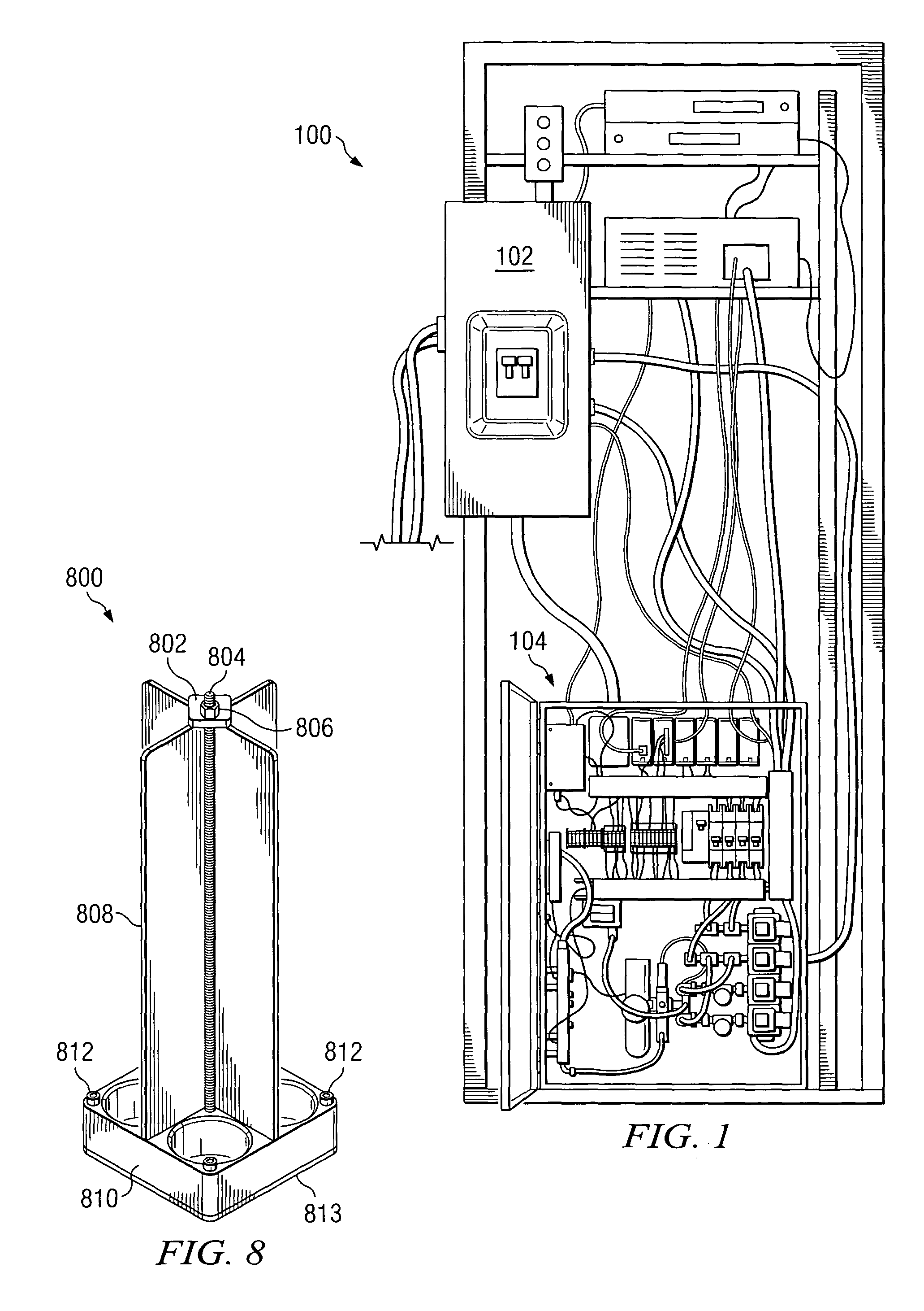
[0021] The present invention is described with reference to the several figures. FIG. 1 shows a rear view of a testing unit consistent with a preferred embodiment. Unit 100 includes equipment necessary for performing testing of chips, such as a nest (not shown, see FIG. 3), thermal control box 104, and power box 102. In addition, innovative testing unit 100 includes a chiller for supplying cooled fluid, and card for receiving the chip to be tested. In a preferred embodiment, the nest centers on the location where the tested chip sockets to the card.

[0022]FIG. 2 shows a detail of the thermal control box. The box 104 is preferably filled with dry air to reduce condensation, as described below. In a preferred embodiment, it includes air / helium controls 202 which provide control for injection of dry air where condensation control is required. Compressed air is also used to drive the cold plate up and down, while helium is preferably used to improve the thermal interface between the chi...


PUM


Abstract

An innovative chip testing system and method includes controlling temperature and condensation during testing. Coarse temperature is controlled by providing a desired fluid flow rate and fluid temperature to a cold plate. Fine temperature control is provided by a feedback loop which controls the power dissipation of cartridge heaters installed within the cold plate. Condensation control is provided by insulating various components of the system, manipulation of dry compressed air in enclosures to reduce surface dew point temperatures, usage of cartridge heaters in a card backside stiffener plate, and by providing a heatsink assembly which prevents condensation on the insulation.

Description

BACKGROUND OF THE INVENTION [0001] 1. Technical Field [0002] The present invention relates generally to integrated circuit (IC) processing and testing, and particularly to temperature and condensation control in a chip tester. [0003] 2. Description of Related Art [0004] High performance processor chips or integrated circuits (ICs) often must be tested and subsequently sorted based on their performance and matched to a given class of machine. Individual chips are tested prior to installation on modules in machines in order to identify chip failures, allowing higher machine manufacturing productivity and improving product quality. Test equipment developed to support performance, productivity and quality is usually required to meet functional test limits defined by several boundary variables such as chip / module voltage, clock speed, power dissipation, and temperature. [0005] Chip testing often requires the chips to be cooled to low temperatures. For example, some processor chip test re...

Claims


Application Information

Patent Timeline
Patent Type & Authority Applications(United States)
IPC IPC(8): G01R31/28
CPCG01R31/2881G01R31/2874
Inventor BEAMAN, DANIEL PAULCORBIN, JOHN SAUNDERS JR.KENT, DALES MORRISONMAHANEY, HOWARD VICTOR JR.PHAN, HOA THANHWRIGHT, FREDERIC WILLIAM IV
Owner IBM CORP
Learn More