Electronic switch
- Summary
- Abstract
- Description
- Claims
- Application Information
AI Technical Summary
Benefits of technology
Problems solved by technology
Method used
Image
Examples
Embodiment Construction
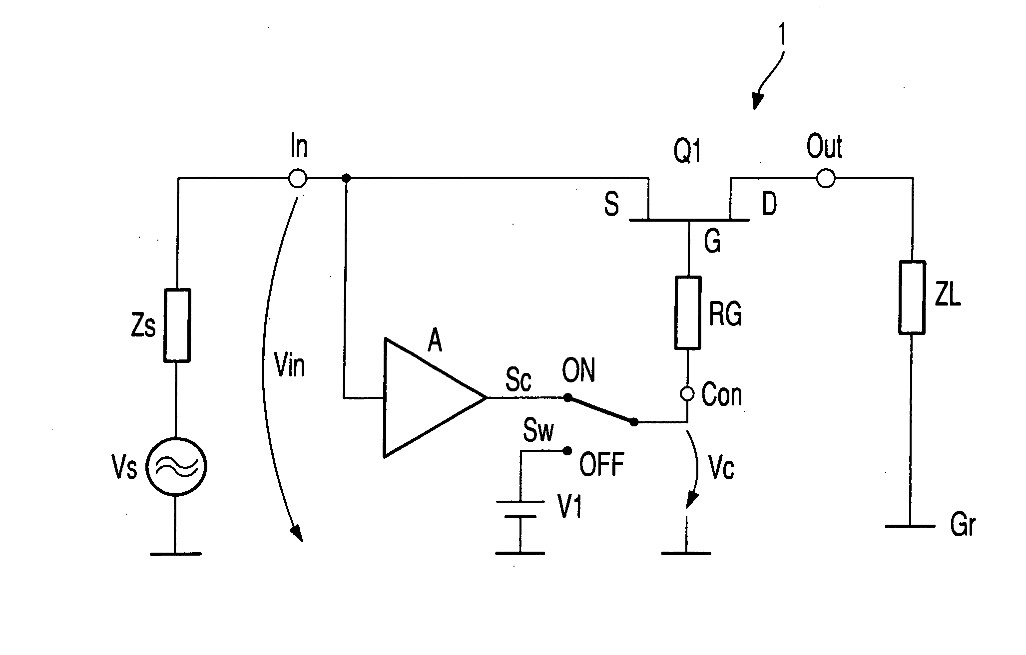
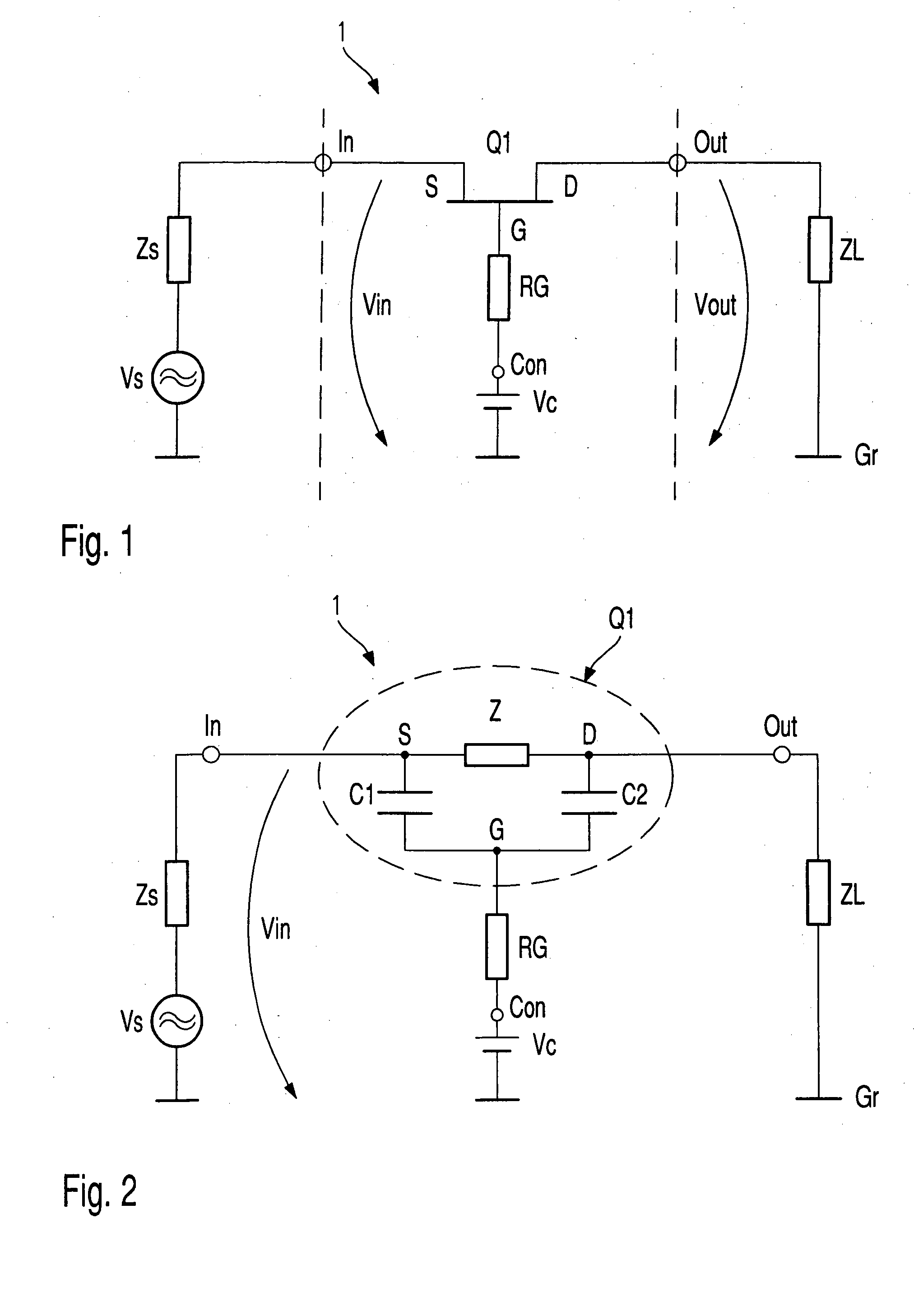
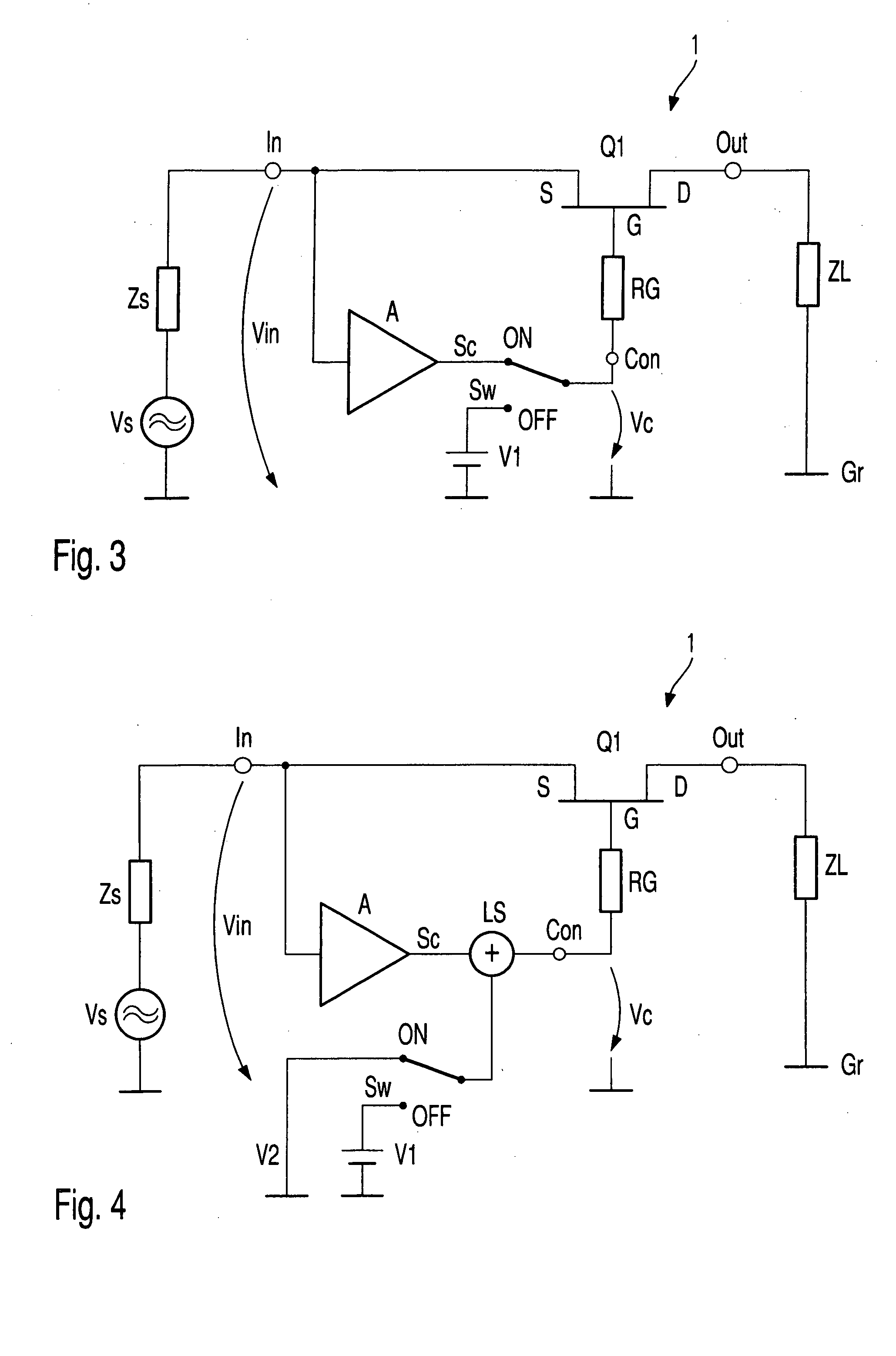
[0023]FIG. 1 shows an electronic switch 1 with an FET Q1 in accordance with the state of the technology. The FET Q1 has a gate terminal G connected to a control port Con through a first resistance RG. Also depicted is a source terminal S connected to an input In and a drain terminal D connected to an output Out. A control signal Vc applied to the control port Con, whose value in this embodiment can assume two different DC voltages, controls the switching state of the electronic switch 1.
[0024] The value of the DC voltage is, for example, altered by a switching apparatus not shown in FIG. 1. Usually one of the two DC values is equal to 0 V, with reference to a common reference potential Gr. With self conducting, n-channel metal semiconductor field-effect transistors, preferred in microwave technology, this value of DC voltage establishes the ON-state. In the ON-state, the FET Q1 switches an input signal Vin, which is present at the input port In directly through to the output port O...
PUM
 Abstract
Description
Claims
Application Information
 - R&D
- Intellectual Property
- Life Sciences
- Materials
- Tech Scout
- Unparalleled Data Quality
- Higher Quality Content
- 60% Fewer Hallucinations
Browse by: Latest US Patents, China's latest patents, Technical Efficacy Thesaurus, Application Domain, Technology Topic, Popular Technical Reports.
© 2025 PatSnap. All rights reserved.Legal|Privacy policy|Modern Slavery Act Transparency Statement|Sitemap|About US| Contact US: help@patsnap.com


