
Microwave amplifier with bypass segment

a micro-wave amplifier and bypass technology, applied in low noise amplifiers, amplifiers with semiconductor devices/discharge tubes, amplifiers with coupling networks, etc., can solve the problems of affecting the operation of the device, and relatively high insertion loss in the bypass mode of the device, so as to reduce the noise factor and reduce input/output reflections

Inactive Publication Date: 2004-03-25
INTEL CORP
View PDF8 Cites 15 Cited by
  • Summary
  • Abstract
  • Description
  • Claims
  • Application Information

AI Technical Summary

Benefits of technology

[0008] A second specific object of the invention is to reduce the noise factor and to reduce input / output reflections in the amplifier unit, when operating in active mode.
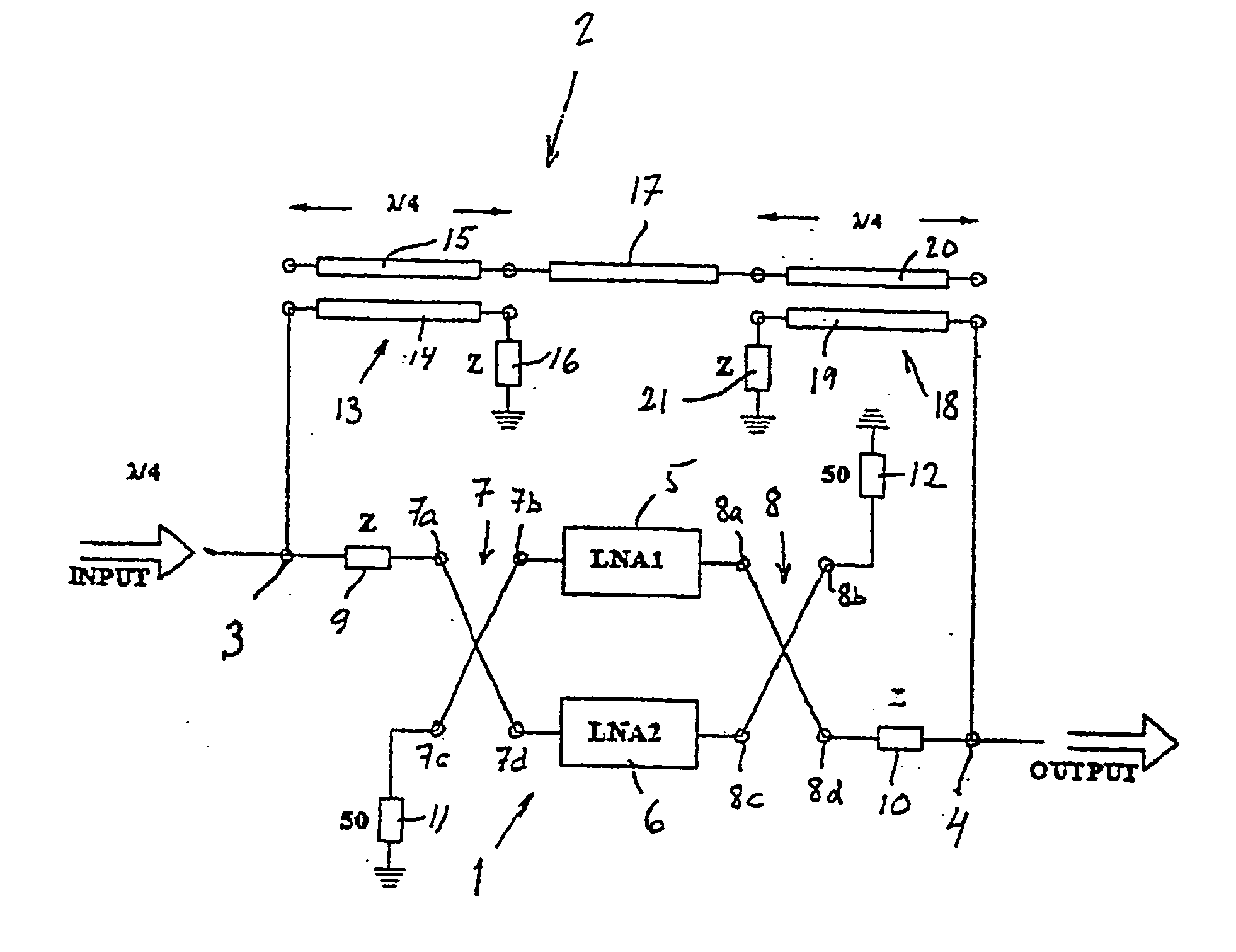
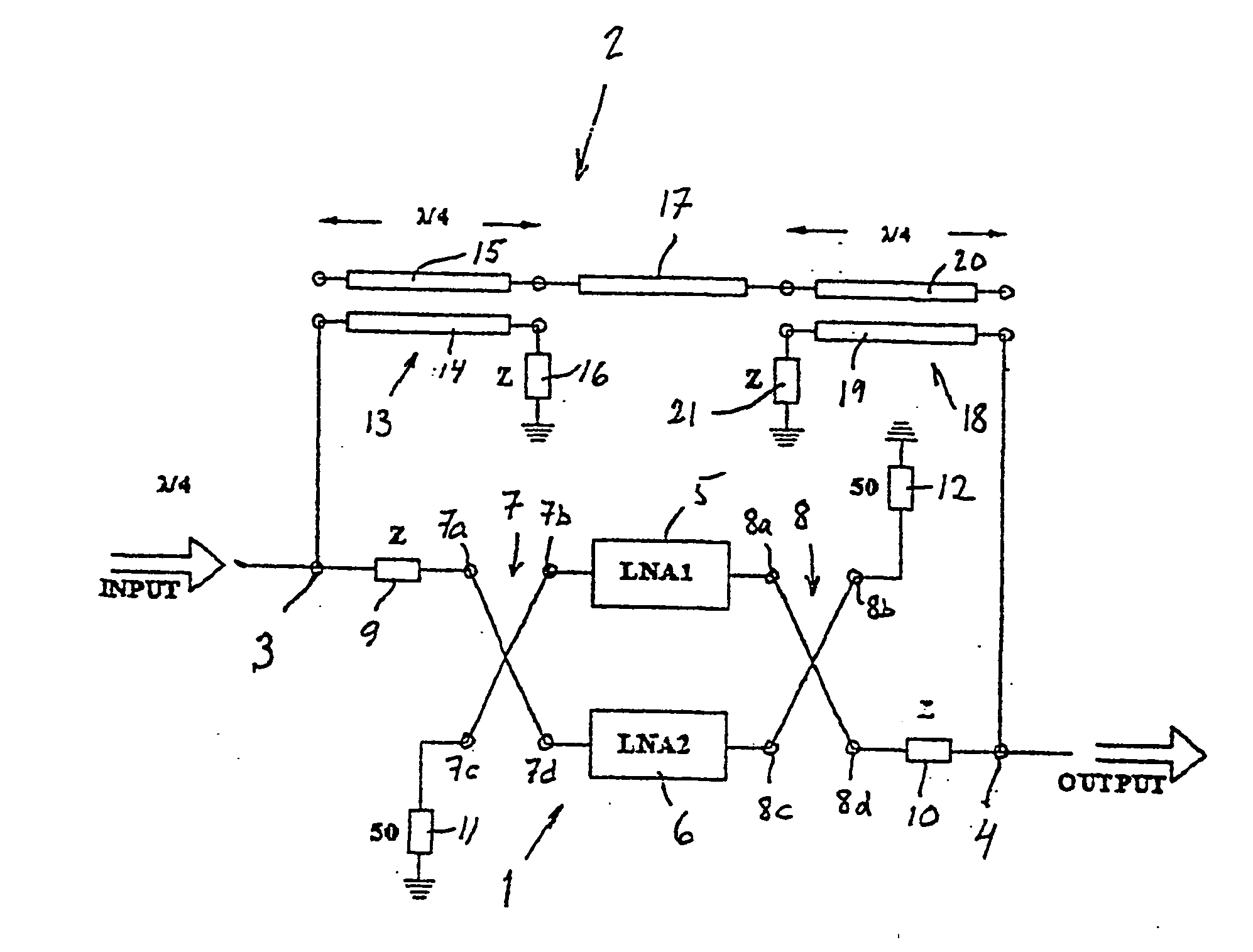
[0009] The above mentioned first object is achieved for a device having the features stated in claim 1. Thus, the bypass segment of the device according to a first aspect of the invention comprises at least one section of coupled transmission lines, whereby the isolation against feedback through the bypass segment is improved.
[0012] Preferably, the input impedance of the bypass segment, in said active mode of the device, is at least an order of magnitude higher than the input impedance of the amplifier unit (typically 50 ohm). In this way, the two low noise amplifiers, arranged in a balanced configuration to form the amplifier unit, are balanced through a wide frequency band, even for frequencies above the predetermined microwave frequency band. Advantageously, such a relatively high input impedance of the bypass segment (in active mode) is combined with the above-mentioned section of mutually coupled transmission lines. Accordingly, it is hereby possible to achieve an increased isolation and stability, a low noise factor and a reduction of the input / output reflections in the amplifier unit when operating in active mode, as well as a reduced insertion loss in the bypass segment when operating in bypass mode.

Problems solved by technology

In case the isolation across the bypass segment in active mode is lower than the amplifier gain, there is a risk of instability due to feedback through the bypass segment.
However, such an arrangement also leads to a relatively high insertion loss in the bypass mode of the device, namely in the order of 2 dB.
This level is a drawback, since it adversely effects the operation of the device in the bypass mode.
A related problem of an amplifier / bypass device of the aforementioned kind is the difficulty in ensuring a proper operation of the device in active mode.

Method used


Image

  • Microwave amplifier with bypass segment
  • Microwave amplifier with bypass segment

Examples


Embodiment Construction

[0016] The circuitry shown on the drawing comprises an amplifier unit 1 with a bypass segment 2 for use, e.g., in combination with an antenna, duplex means, and band-pass filters at the top of an antenna mast or tower in a cellular mobile telephone system, as explained in the above-mentioned U.S. Pat. No. 5,821,811.

[0017] The amplifier unit 1 has the task of amplifying received communication signals, in a predetermined microwave frequency band in a frequency range above 500 MHz, before these signals become significantly attenuated along a transmission line (not shown) to a base station located adjacent to the bottom of the antenna mast or tower.

[0018] The amplifier unit 1 is inserted between an input port 3 and an output port 4, the bypass segment 2 being arranged in parallel to the amplifier unit 1, likewise between the input and output ports 3,4.

[0019] As previously known per se (see the above-mentioned U.S. Pat. No. 4,825,177), the amplifier unit comprises two low noise amplifier...


PUM


Abstract

A microwave amplifier device with a bypass segment, the device operating either in active mode or in bypass mode. The bypass segment (2) comprises at least one section (13) of coupled transmission lines (14,15) whereby the isolation is increased. The amplifier unit (1) includes two LNAs arranged in parallel in a balanced configuration, and the bypass segment (2) has a relatively high input impedance in active mode, whereby a balanced operation of the amplifier unit is maintained. Consequently, a low noise factor is obtained, as well as reduced input and output reflections.

Description

[0001] The present invention relates to a device for amplifying communication signals in a predetermined microwave frequency band above 500 MHz. A bypass segment is automatically activated when the amplifier unit becomes inoperative, e.g. due to failure of some RF component or DC failure, and is effectively blocked during normal operation of the amplifier unit. More particularly, the device is of the kind defined in the preamble of appended claim 1.BACKGROUND OF THE INVENTION AND RELATED ART[0002] A device of the aforementioned kind is disclosed in U.S. Pat. No. 5,821,811 (Allgon AB). In the known device, the amplifier unit forms a closed loop together with the bypass segment. In case the isolation across the bypass segment in active mode is lower than the amplifier gain, there is a risk of instability due to feedback through the bypass segment.[0003] In order to secure sufficient stability, the isolation in the bypass segment should be at least 10 dB higher than the gain of the amp...

Claims


Application Information

Patent Timeline
IPC IPC(8): H03F3/60
CPCH03F3/602H03F2200/372H03F2200/294H03F2200/198
Inventor POZDEEV, OLEG
Owner INTEL CORP
Learn More