
Method of manufacturing semiconductor device having thin film SOI structure

a technology of thin film and semiconductor devices, which is applied in the direction of semiconductor devices, semiconductor/solid-state device details, electrical equipment, etc., can solve the problems of less silicon in the soi layer to be consumed, and difficult to control the composition in order

Inactive Publication Date: 2005-01-27
LAPIS SEMICON CO LTD
View PDF3 Cites 5 Cited by
  • Summary
  • Abstract
  • Description
  • Claims
  • Application Information

AI Technical Summary

Benefits of technology

[0011] An objective of the invention is to resolve the above-described problem and to provide a method of forming a semiconductor device, which avoid reaching a contact hole to a support substrate of a SOI substrate through a BOX layer.
[0012] The objective is achieved by a method of manufacturing a semiconductor device, including the steps of, (1) preparing an SOI substrate, (2) forming a metal layer on the SOI substrate, (3) performing a first anneal treatment to the metal layer at a relatively low temperature in order to transform the metal layer to a first silicide layer, (4) forming an insulating layer on the first silicide layer, and (5) forming a contact hole, which reaches the first silicide layer, in the insulating layer; and (6) performing a second anneal treatment to the silicide layer at a relatively high temperature in order to transform the first silicide layer to a second silicide layer.

Problems solved by technology

However, the thinner the SOI layer is, the lesser the amount of silicon in the SOI layer to be consumed is.
As a result, when the silicide layer is formed with using the thin SOI layer, it is difficult to control the composition in order to form the silicide layer consistently.
Further, since the thickness of the SOI layer is reduced gradually by factors presented in each of the process steps before silicidation, it is further difficult to control the composition in order to form the silicide layer.

Method used


Image

  • Method of manufacturing semiconductor device having thin film SOI structure
  • Method of manufacturing semiconductor device having thin film SOI structure
  • Method of manufacturing semiconductor device having thin film SOI structure

Examples


Embodiment Construction

[0016] In each drawing, the same reference numbers designate the same or similar components.

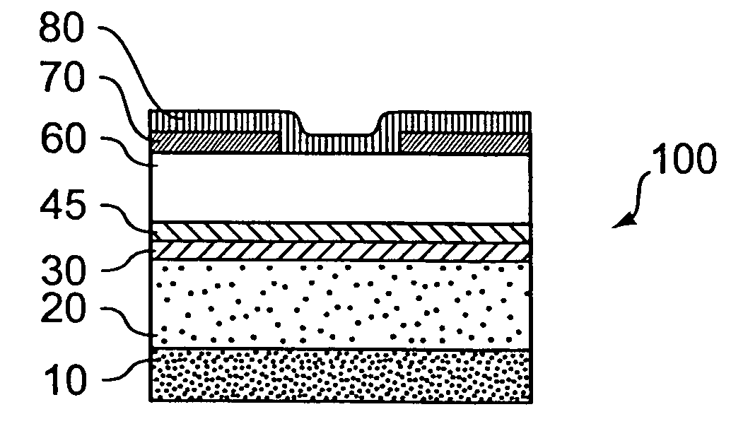
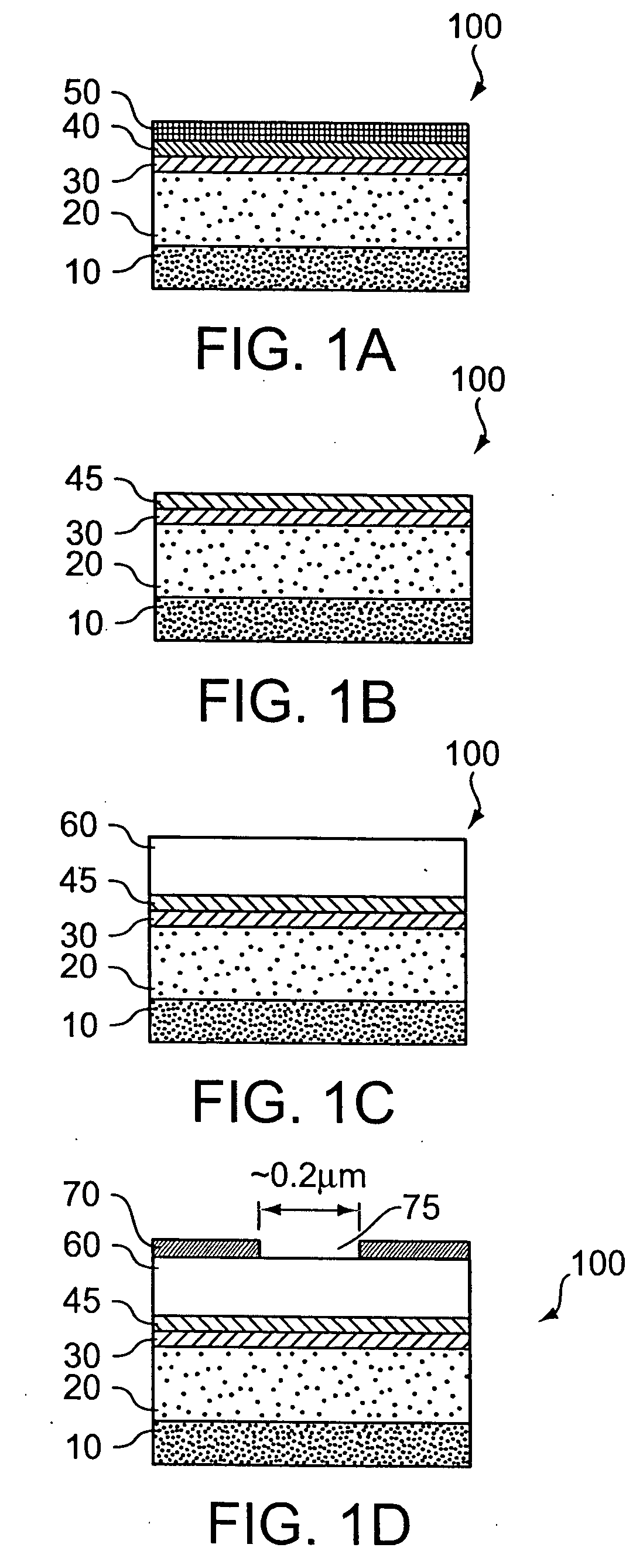
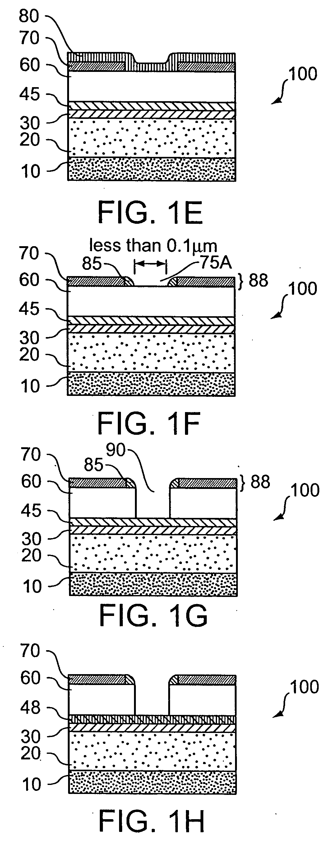
[0017]FIGS. 1A through 1H shows successive stages in manufacturing an SOI-type semiconductor device 100. Referring to FIG. 1A, a buried silicon oxide layer (BOX layer) 20 is formed on an entire surface of a support substrate 10 made of silicon. Then, a silicon-on-insulator layer (SOI layer) 30 is formed on an entire surface of the BOX layer 20. An SOI substrate consists of the support substrate, the BOX layer and the SOI layer. Then, a cobalt layer (Co layer) 40 having an appropriate thickness is formed on the SOI layer 30 by a conventional sputtering method. After forming the Co layer 40, a titanium nitride layer (TiN layer) 50 is formed on the Co layer 40 by a conventional sputtering method. The TiN layer 50 acts as a cap layer to protect the reaction of the Co layer 40 with the SOI layer from the atmosphere in a successive silicidation process.

[0018] Referring toFIG. 1B, a first anneal t...


PUM

PropertyMeasurementUnit
temperatureaaaaaaaaaa

Abstract

A method of manufacturing a semiconductor device includes the steps of, (1) preparing an SOI substrate, (2) forming a metal layer on the SOI substrate, (3) performing a first anneal treatment to the metal layer at a relatively low temperature in order to transform the metal layer to a first silicide layer, (4) forming an insulating layer on the first silicide layer, and (5) forming a contact hole, which reaches the first silicide layer, in the insulating layer; and (6) performing a second anneal treatment to the silicide layer at a relatively high temperature in order to transform the first silicide layer to a second silicide layer.

Description

CROSS-REFERENCE TO RELATED APPLICATION [0001] This application claims the priority benefit of Japanese Patent Application No. 2001-384956, filed Dec. 18, 2001, the entire disclosure of which is incorporated herein by reference. BACKGROUND OF THE INVENTION [0002] 1. Field of the Invention [0003] The invention relates to a method of manufacturing a semiconductor device, specifically to a method of manufacturing a semiconductor device having a thin film SOI structure in which imperceptible contact holes are formed. [0004] 2. Description of the Related Art [0005] With an increase in the level of a high performance, an SOI-type semiconductor device is generally used in order to satisfying the requirement, instead of a semiconductor device having a bulk silicon substrate. The SOI-type semiconductor device includes an SOI substrate, which consists of a support substrate, a buried silicon oxide layer (BOX layer) and a silicon layer (SOI layer) formed on the BOX layer, and field effect trans...

Claims


Application Information

Patent Timeline
Patent Type & Authority Applications(United States)
IPC IPC(8): H01L21/3205H01L21/336H01L21/28H01L21/762H01L21/768H01L23/52H01L29/786
CPCH01L21/7624H01L21/76264H01L2924/0002H01L2924/00H01L21/76816
Inventor IKEGAMI, NAOKATSU
Owner LAPIS SEMICON CO LTD
Learn More