
Exhaust gas cleaner for internal combustion engine with particulate filter having heat-absorbing area

a technology of exhaust gas cleaner and particulate filter, which is applied in the direction of machines/engines, separation processes, transportation and packaging, etc., can solve the problems of rapid chain reaction, inability to absorb pm combustion heat, and rapid burn of pm, and achieve the effect of increasing the heat capacity of the cellular walls

Inactive Publication Date: 2005-01-20
DENSO CORP
View PDF11 Cites 28 Cited by
  • Summary
  • Abstract
  • Description
  • Claims
  • Application Information

AI Technical Summary

Benefits of technology

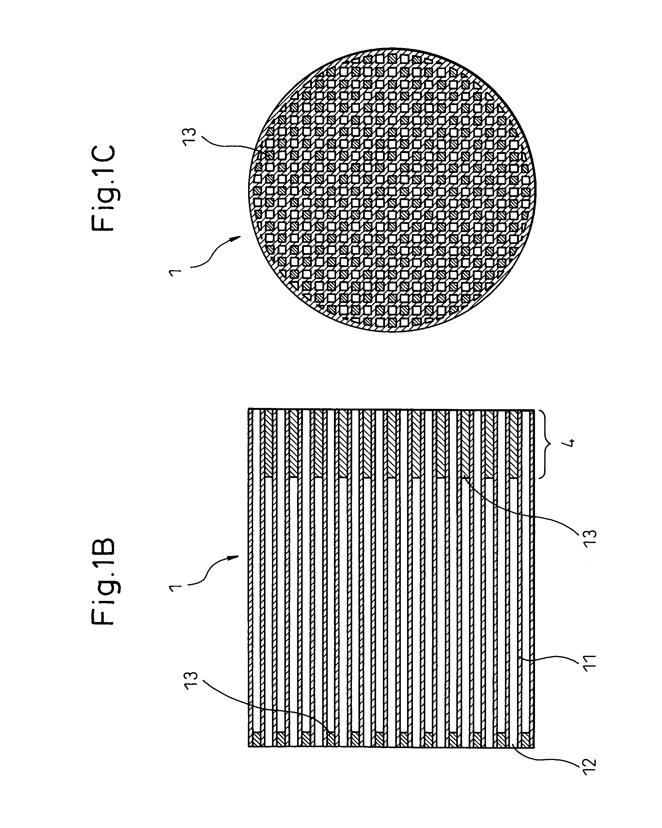
[0012] According to the above structure, as the combustion heat is absorbed and dissipated by the heat-absorbing area even if the rapid chain reaction of PM combustion occurs due to the abrupt deceleration of the engine or others, the temperature rise of the particulate filter, particularly at the exhaust gas flowing-out side end liable to be high temperature can be suppressed to lower the maximum temperature thereof. Thereby, since it is possible to deposit a larger amount of PM in the particulate filter while preventing the catalyst carried on the particulate filter from being deteriorated and the filter matrix from being damaged, the safety and the economic superiority are improved without deteriorating the fuel consumption caused by the frequent regeneration thereof.
[0032] As the coated member carrying the catalyst is the heat-capacitated material, it is also possible to increase the heat capacity of the cellular walls by thickening the catalyst-coated layer. The same effect as described above is obtainable by making the cellular walls with a catalyst-coated layer to make a heat-absorbing area.

Problems solved by technology

As the pressure loss of the particulate filter increases when an amount of deposited PM increases, to result in an inconvenience such as the lowering of engine output, the regeneration treatment for burning and removing the collected PM is intermittently carried out so that the particulate filter is continuously usable.
However, if PM is excessively deposited, there is a problem in that PM quickly burns in a chain reaction during the regeneration treatment or when the engine is abruptly decelerated in high speed driving.
At this time, when the flow rate of the exhaust gas is suddenly lowered, for example, due to the abrupt deceleration, it is not possible to absorb the combustion heat of PM.
Accordingly, the temperature of the downstream part of the particulate filter in a hot state rises further to cause the self-combustion of PM, resulting in a rapid chain reaction.
The rapid combustion of PM described above causes the deterioration of catalyst and, in an extreme case, the thermal destruction (cracking or melting) of a matrix of the particulate filter results.
That is, according to these countermeasures, as the temperature rise of the particulate filter itself is not prevented, the risk of damage caused by the high temperature is not eliminated when the rapid chain reaction of PM combustion occurs due to the operation condition.
Also, there is another problem in that, when the particulate filter is coated with a catalyst, a catalyst may be deteriorated.
In the prior art, to prevent the particulate filter from damage, an allowable limit amount of PM to be deposited is set at a low level and the particulate filter is frequently regenerated, which causes a serious problem in that the fuel consumption is deteriorated.

Method used


Image

  • Exhaust gas cleaner for internal combustion engine with particulate filter having heat-absorbing area
  • Exhaust gas cleaner for internal combustion engine with particulate filter having heat-absorbing area
  • Exhaust gas cleaner for internal combustion engine with particulate filter having heat-absorbing area

Examples


first embodiment

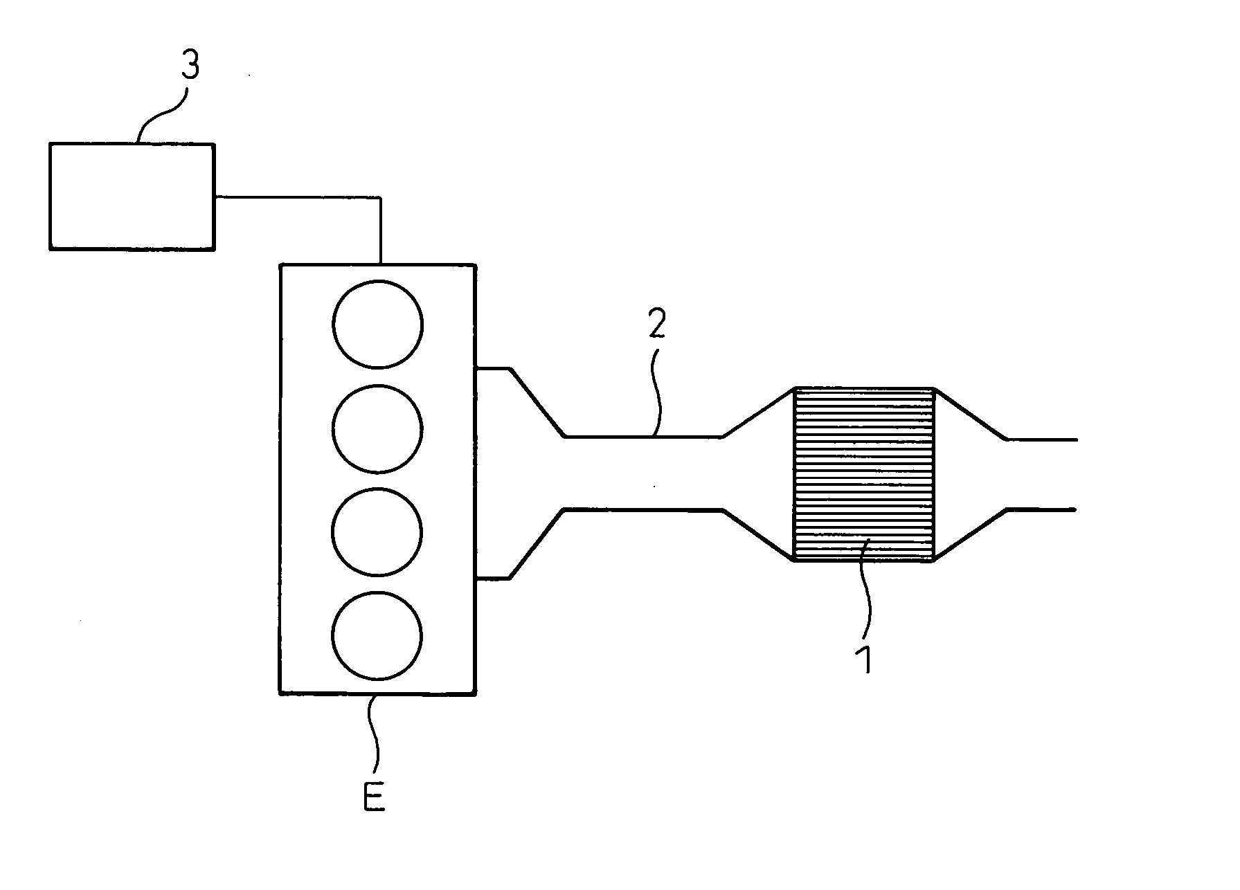
[0053] the present invention will be described in detail below with reference to the attached drawings. FIG. 1A is a schematic view showing a whole construction of an exhaust gas cleaner for an internal combustion engine to which the present invention is applied. As illustrated, an exhaust pipe 2 of an internal combustion engine E has a large diameter portion on its way for accommodating a particulate filter 1 therein. The internal combustion engine E is, for example, a diesel engine, and the particulate filter 1 is a diesel particulate filter (DPF) for collecting particulates (PM) exhausted from the diesel engine. The particulate filter 1 is regenerated by burning to remove the collected PM at suitable times by using a particulate filter regenerating means 3.

[0054] As shown in FIGS. 1B and 1C, the particulate filter 1 has a columnar monolithic structure internally partitioned by porous cellular walls 11 extended in an axial direction of the filter 1 to have a number of cells 12 arr...

second embodiment

[0059] As shown in FIGS. 2A and 2B, the particulate filter 1 may have a heat-absorbing area 4 formed by a structure in that all the clogged sections 13 provided at the exhaust gas flowing-out side end are deeply clogged (see FIG. 2A) or a structure in that part of the clogged sections 13 provided at the exhaust gas flowing-out side end are solely deeply clogged at a predetermined depth in a second embodiment as shown in FIG. 2B. While the deeply clogged sections 13A and the normally clogged sections 13B are substantially uniformly arranged in the latter case, a ratio or the arrangement thereof may be changed and suitably determined so that the maximum temperature does not exceed the allowable limit based on the temperature distribution in the particulate filter 1 during the regeneration thereof. In such a manner, if all the clogged sections 13 in the heat absorbing area 4 are not deeply clogged but the deeply clogged sections are selectively provided, it is possible to provide an ef...

third embodiment

[0060] shown in FIG. 3, the deeply clogged section 13A constituting the heat absorbing area 4 is not arranged in an outer circumferential regions 14 of the particulate filter 1, but the deeply clogged sections 13A having a predetermined depth are solely arranged in a central region and the vicinity thereof. In the drawing, while the deeply clogged sections 13A having a predetermined depth and the sections 13B having an normal depth are substantially uniformly arranged in the central region and the vicinity thereof, the deeply clogged structure may be provided in all the central region and the vicinity thereof in the particulate filter 1 except for the outer circumferential regions 14 thereof. As the outer circumferential region 14 dissipates heat more easily than the central region because the former is brought into contact with a wall of the exhaust pipe 2, a risk of exceeding the allowable temperature is less even if it does not rely on the deeply clogged structure. Accordingly, ...


PUM

PropertyMeasurementUnit
porosityaaaaaaaaaa
thicknessaaaaaaaaaa
axial lengthaaaaaaaaaa

Abstract

To prevent the deterioration of catalyst or the damage of a particulate filter caused by the rapid temperature rise of the particulate filter when the abrupt deceleration of an engine occurs, and avoid the deterioration of fuel consumption by depositing a large PM in the particulate filter and regenerating the same at once. A heat-absorbing area 4 is provided by forming a deeply clogged structure at the exhaust gas flowing-out side end of the particular filter 1 disposed in an exhaust pipe 2 of an internal combustion engine E. As the heat-absorbing area has a heat capacity larger than that in the other portions, the combustion heat is absorbed and dispersed even if the rapid chain reaction of PM combustion occurs, whereby it is possible to suppress the temperature rise of the downstream portion of the particulate filter liable to be high in temperature.

Description

BACKGROUND OF THE INVENTION [0001] 1. Field of the Invention [0002] The present invention relates to an exhaust gas cleaner provided with a particulate filter for collecting particulates contained in exhaust gas of an internal combustion engine and, more specifically, to a particulate filter structure capable of restricting the quick combustion of particles when the particulate filter is regenerated. [0003] 2. Description of the Related Art [0004] Various devices have been proposed as environmental countermeasures for reducing the amount of particulates (particle material; hereinafter referred to as PM) exhausted from a diesel engine. Typically, a system has been known in which a particulate filter, such as one coated with catalyst on its surface, is provided in an exhaust pipe to collect PM. A particulate filter has a number of cells as gas passages and is adapted to adsorb and collect PM when exhaust gas passes through porous partition walls separating many such cells from each ot...

Claims


Application Information

Patent Timeline
Patent Type & Authority Applications(United States)
IPC IPC(8): F01N3/02B01D46/24B01D46/42B01D53/94F01N3/022F01N3/023F01N3/035
CPCB01D46/2429F01N2510/06B01D46/2444B01D46/2455B01D46/2459B01D46/2466B01D46/2474B01D2046/2433B01D2046/2496F01N3/0222F01N3/023F01N3/035F01N2240/10F01N2260/10F01N2330/32B01D46/244B01D46/2498B01D46/24491B01D46/2476B01D46/24494
Inventor SAITO, MAKOTOYAHATA, SHIGETOTOCHIKAWA, KAZUHARUTOKUDA, KOJIRO
Owner DENSO CORP
Learn More