Power generating device

a power generation device and power generation technology, applied in the direction of electrochemical generators, machines/engines, liquid fuel engines, etc., can solve the problems of short life of the turbo-air compressor, high noise, and high power consumption, so as to reduce the power consumption of the air compressor, prolong the life of the compressor, and suppress the deformation of the revolution scroll member

Inactive Publication Date: 2005-01-06
MATSUSHITA SEIKO CO LTD
View PDF2 Cites 11 Cited by
  • Summary
  • Abstract
  • Description
  • Claims
  • Application Information

AI Technical Summary

Benefits of technology

[0022] It is another object of the invention to suppress the deformation of the revolution scroll member ca...

Problems solved by technology

Thus, there is a problem that lifetime of the turbo-air compressor is as short as 5,000 hours, and its noise is also high.
Although high pressure can be generated as compared with circumferential speed, there is a problem that power consumption is high, operation efficiency is low and noise is high.
Further, since the thickness of the eccentric shaft 103a can not be increased, the revolution scroll member 101 is bent by the bending moment M, the drive shaft 103 and the eccentric shaft 103a can not be kept in parallel to each other, and this may cause a noise.
However, the electric power generator in which the above-described conventional scroll compressor is utilized as the air compressor has the following problems.
First, since synthetic resin is used for the revolution scroll member of the scroll compressor, if a metal part is inserted into the synthetic resin turning scroll to reinforce the receiving portion which receives the eccentric rotation, coefficients of linear expansion of the synthetic resin and the metal part are different from each other, the turning scroll is deformed by heat generated at the time of insert injection molding or change in time during use.
If such a deformation is generated, the gap between the turning scroll lap and the fixed scroll lap can not be maintained at constant, lap contact is generated, and this causes no...

Method used


Image

  • Power generating device
  • Power generating device
  • Power generating device

Examples


embodiment 1

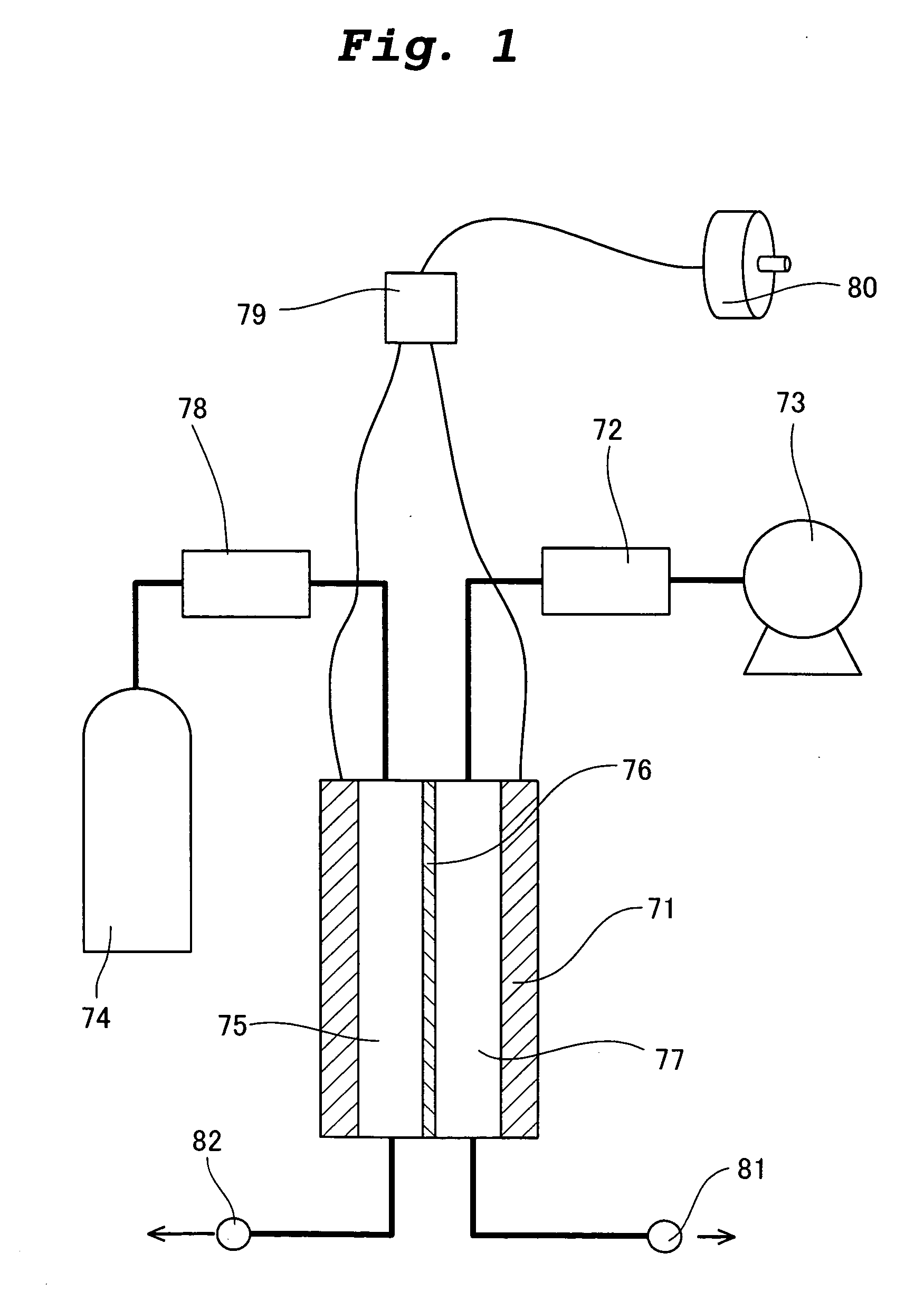
[0065] An electric power generator according to an embodiment of the present invention will be explained with reference to the drawings. FIG. 1 is a block diagram of the electric power generator of the invention.

[0066] A structure of the electric power generator using a polyelectrolyte fuel cell according to this embodiment is as follows. That is, a fuel cell 71 comprises a fuel pole 75, an electrolytic film 76 and an air pole 77. Air is pressurized by an air compressor 73 and is humidified by an air humidifier 72, and is supplied to an air pole 77. Hydrogen is adjusted in pressure at a pressure governor valve (not shown) from a hydrogen bomb 74, humidified by a hydrogen humidifier 78, and supplied to a fuel pole 75. According to the above structure, in the fuel cell 71, hydrogen supplied to the fuel pole 75 becomes hydrogen ion, the hydrogen ion passes through the electrolytic film 76 and is moved to the air pole 77. In the air pole 77, the transmitted hydrogen ion and oxygen in t...

embodiment 2

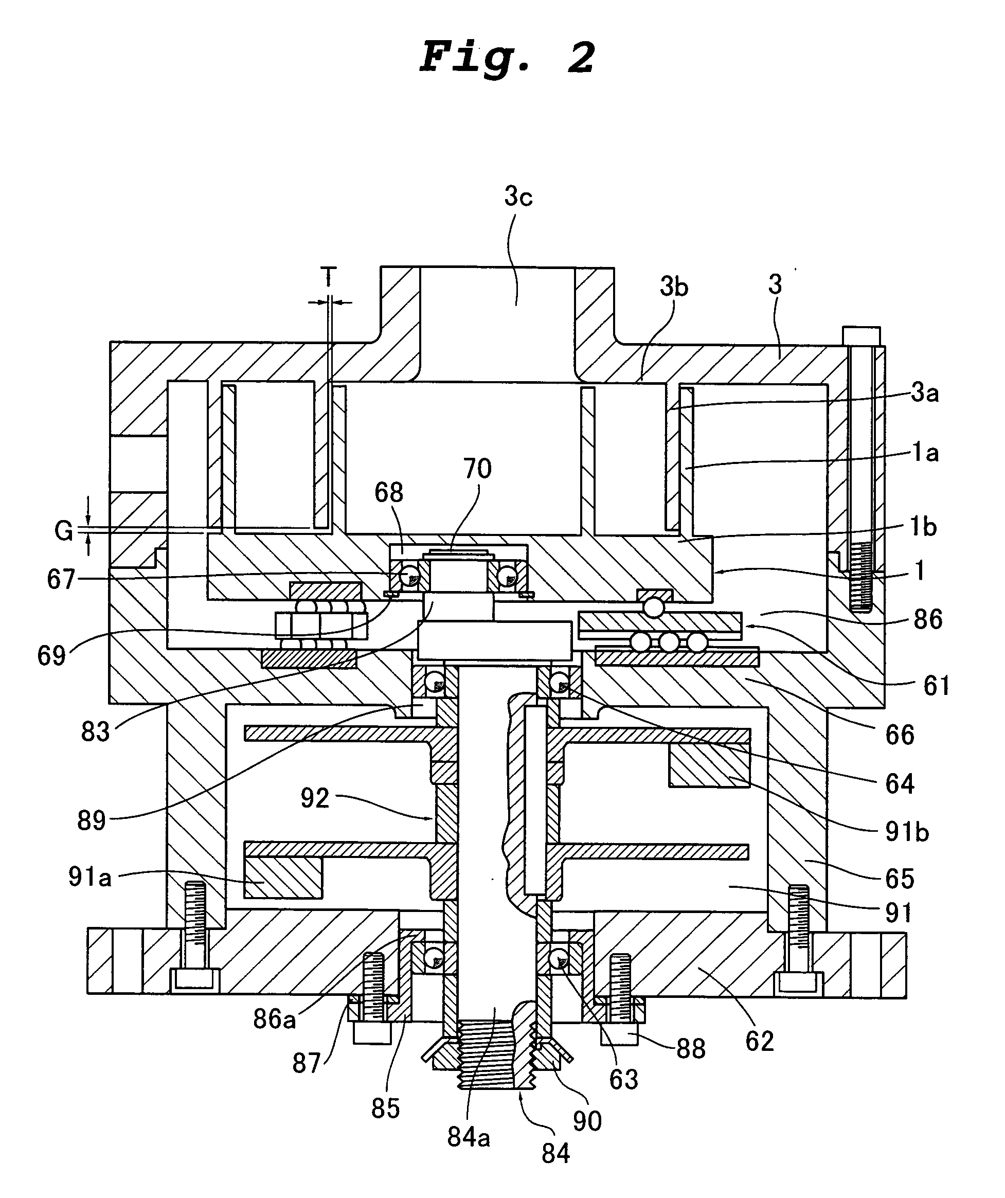
[0067] An air compressor of an embodiment used in the electric power generator of the invention will be explained next. FIG. 2 is a sectional view showing the air compressor of the embodiment of the invention. A drive motor for driving a compressing mechanism is not illustrated in the drawing.

[0068] A scroll compressor as an air compressor shown in FIG. 2 includes a revolution scroll member 1 and a fixed scroll member 3. According to the revolution scroll member 1, a revolution scroll lap 1a stands on a revolution lap support disk 1b having a revolution shaft support hole 68. A drive shaft 84 includes a main shaft 84a provided at its end with an eccentric shaft 83. The eccentric shaft 83 is eccentric from the main shaft 84a. A ball bearing 67 is fitted over the eccentric shaft 83. The revolution scroll member 1 is pivotally supported by the drive shaft 84 through the ball bearing 67.

[0069] The eccentric shaft 83 is provided with a shaft C shaped detent ring 70 so that the eccentri...

embodiment 3

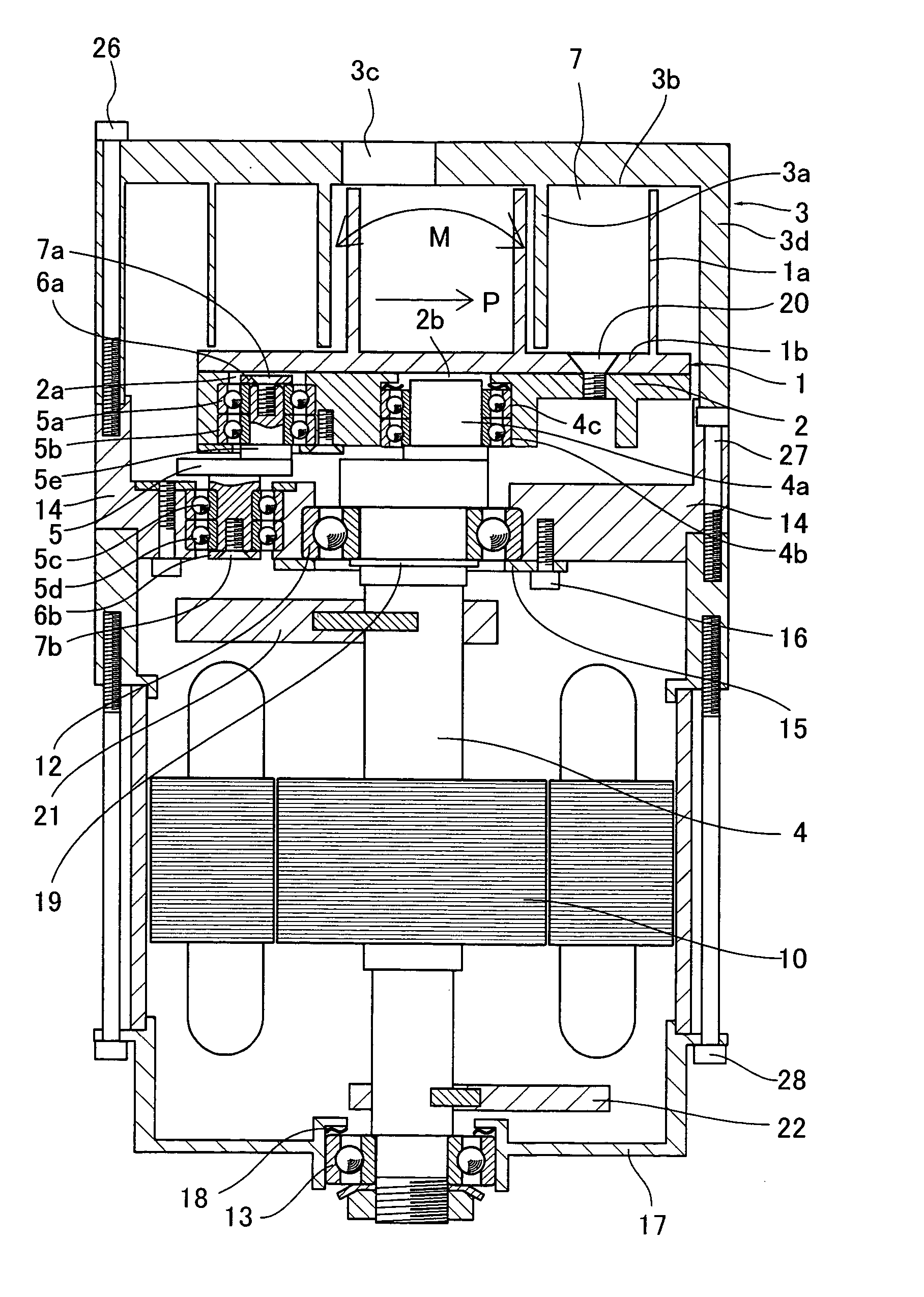
[0079] An air compressor according to another embodiment used for the electric power generator of the invention will be explained next with reference to the drawings. FIG. 3 is a sectional view showing the air compressor of the other embodiment of the invention.

[0080] A scroll compressor as the air compressor shown in FIG. 3 comprises a compressing mechanism, a scroll drive section and an assembling bolt. The compressing mechanism comprises a revolution scroll member 1 which engages with a revolution disk 2, and a fixed scroll member 3. The scroll drive section comprises a revolution support plate 14, a drive motor 10 having a drive shaft 4 which is to be inserted into the revolution support plate 14, and a balance protection cover 17 for protecting the drive motor 10 and a balancer weight 22. Detailed structure will be explained.

[0081] A revolution scroll lap 1a stands on one of surfaces of a revolution lap support disk 1b of a revolution scroll member 1. The revolution lap suppo...


PUM


Abstract

In a scroll compressor, a revolution scroll lap 1a stands on one of surfaces of a revolution lap support disk 1b of a revolution scroll member 1, and a revolution disk 2 is connected to the other surface. The revolution disk 2 is formed at its center with a revolution shaft support hole 2b into which an eccentric shaft 4a is to be inserted. An outer periphery of the revolution shaft support hole 2b is formed with a crankshaft support hole 2a into which an eccentric shaft 5e is to be inserted. The eccentric shaft 5e restrains the rotation of the revolution scroll member 1. The revolution scroll lap 1a and the revolution lap support disk 1b are integrally formed of synthetic resin. The revolution disk 2 is made of metal. The revolution shaft support hole 2b and the crankshaft support hole 2a are integrally formed together. With this configuration, the thermal deformation of revolution scroll member 1 is suppressed, and wear and mechanical loss caused by contact between laps are prevented.

Description

TECHNICAL FIELD [0001] The present invention relates to an electric power generator utilizing a scroll compressor as an air compressor. BACKGROUND TECHNIQUE [0002] A turbo-air compressor and a swirl air compressor are used as air compressors which supply air and which are utilized in polyelectrolyte fuel cells which are electric power generators. A turbo-air compressor is an air compressor in which a turbofan is rotated at high speed to increase the pressure by a centrifugal force. The turbo-air compressor is incorporated in a home vacuum cleaner, and the turbo-air compressor is normally rotated at high speed of 15,000 to 25,000 rpm. Thus, there is a problem that lifetime of the turbo-air compressor is as short as 5,000 hours, and its noise is also high. A swirl air compressor is an air compressor in which a rotation disk having a large number of radial grooves along its outer periphery causes turbulent flow and shearing effect to increase the pressure. Although high pressure can be...

Claims


Application Information

Patent Timeline
IPC IPC(8): F01C17/06F04C18/02F04C23/00F04C29/00H01M8/04H01M8/10
CPCF01C17/063F04C18/0253F04C23/008Y02E60/50F05C2225/00H01M8/04089F04C29/0021
Inventor OKAYAMA, TOYOJIOGINO, KAZUOKATO, TSUTOMUTANIGUCHI, KAZUHIRO
Owner MATSUSHITA SEIKO CO LTD
Why Eureka
Try Eureka