Bone fixation apparatus

Inactive Publication Date: 2005-06-14
U & I INC
View PDF21 Cites 161 Cited by
  • Summary
  • Abstract
  • Description
  • Claims
  • Application Information

AI Technical Summary

Benefits of technology

[0012]The present invention provides a bone fixation apparatus with an improved supporting force of a bone screw, thereby preventing movement of a bone, and at the same time, is assembled in an easy manner.
[0013]According to an embodiment of the present invention, there is provided a bone fixation apparatus comprising: a bone screw having a head; a cap member placed on an upper part of the head of the bone screw; a receiver member having a bore in which the cap member and the head of the bone screw are respectively accommodated and held and a U-shaped channel through which a support bar extends; and a compression member threadedly coupled into the receiver member to downwardly bias the support bar; wherein a multitude of stepped portions are formed at a lower end of and on an inner surface of the receiver member to be brought into linear contact with an outer surface of a lower part of the head so that the supporting force for the head of the bone screw is increased.
[0017]According to another embodiment of the present invention, the internal threads comprise trapezoidal threads, so that deformation of the receiver member can be prevented and the internal threads can provide optimized results in terms of force transfer, locking efficiency, and prevention of unscrewing.
[0018]According to still another embodiment of the present invention, the trapezoidal thread has an upper surface which is formed to have a slope greater than that of the lower surface, so that the cap member and the compression member can be easily assembled while preventing the cap member from being unintentionally unscrewed.

Problems solved by technology

However, in the former bone fixation apparatus as described in Korean Patent Laid-open Publication No. 2000-48562, the head 12 supported in the tapered recess 16 is likely to be moved by an external factor because the supporting force is insufficient.
The latter type bone fixation apparatus as described in U.S. Pat. No. 6,280,442, while coping to some extent the problem caused in Korean Patent Laid-open Publication No. 2000-48562, suffers from defects in that it is difficult to fit the retainer ring 38 in place, and the supporting force of the bone screw is still insufficient.
When the head of the bone screw is supported by the cap member threadedly coupled to the receiver member, it is not easy to screw the cap member adjacent to the lower end of the receiver member.
Further, because the biasing force of the compression member cannot be transferred to the head, assemblability is deteriorated and the supporting force of the bone screw is downgraded.

Method used


Image

  • Bone fixation apparatus
  • Bone fixation apparatus
  • Bone fixation apparatus

Examples


Embodiment Construction

[0030]Reference will now be made in greater detail to a preferred embodiment of the invention, an example of which is illustrated in the accompanying drawings. Wherever possible, the same reference numerals will be used throughout the drawings and the description to refer to the same or like parts.

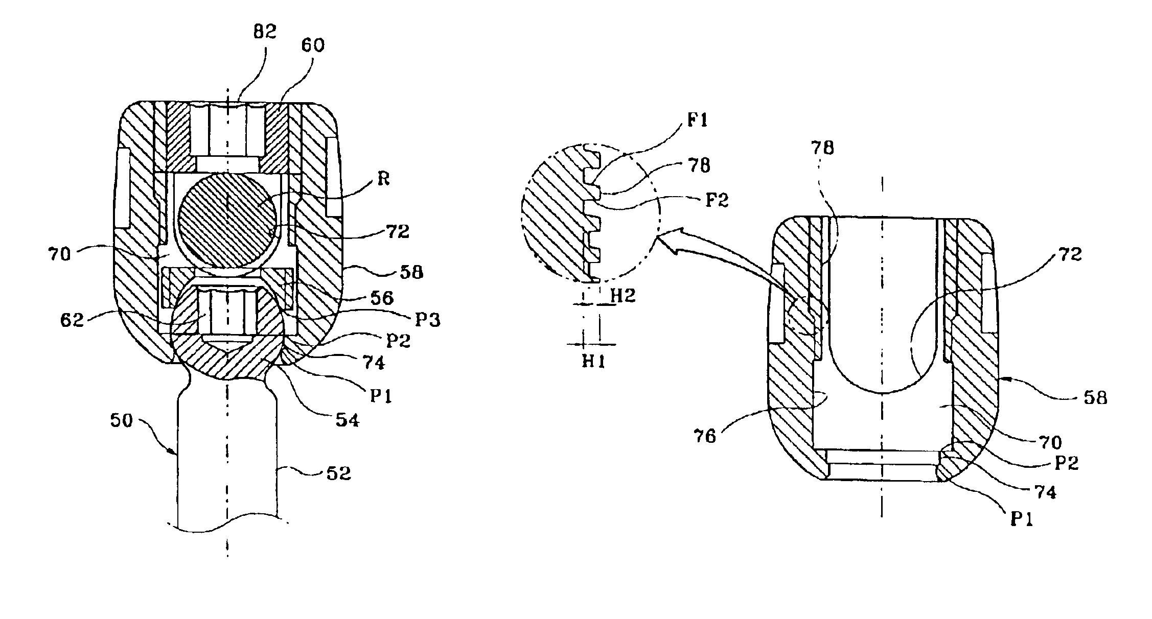
[0031]As shown in FIGS. 3 and 4, a bone fixation apparatus in accordance with an embodiment of the present invention includes a bone screw 50 which has external threads 52 and a head 54. An upper part of the head 54 of the bone screw 52 is supported by a cap member 56. The bone fixation apparatus further includes a receiver member 58 in which the head 54, the cap member 56 and a support bar R are accommodated and fixedly held. A compression member 60 for fixing the support bar R is threadedly coupled into an upper part of the receiver member 58.

[0032]The external threads 52 of the bone screw 50 are screwed into a bone. The lower end of the external threads 52 is pointed to be easily screwe...


PUM


Abstract

Disclosed is a bone fixation apparatus. This device comprises a bone screw having a head; a cap member placed on an upper part of the head of the bone screw; a receiver member having a bore in which the cap member and the head of the bone screw are respectively accommodated and held, and a U-shaped channel through which a support bar extends; and a compression member threadedly coupled into the receiver member to downwardly bias the support bar. A multitude of stepped portions are formed at a lower end and inner surface of the receiver member to be brought into linear contact with an outer surface of a lower part of the head so that the supporting force for the head of the bone screw is increased.

Description

FIELD OF THE INVENTION[0001]The present invention relates to a bone fixation apparatus which is used for fixing and stabilizing a bone such as the spine, and so forth, after the bone is corrected into its normal state.BACKGROUND OF THE INVENTION[0002]Various bone fixation apparatuses have been disclosed in the art, such as those described in Korean Patent Laid-open Publication No. 2000-48562 and U.S. Pat. No. 6,280,442.[0003]As shown in FIG. 1, the bone fixation apparatus described in Korean Patent Laid-open Publication No. 2000-48562 includes a bone screw 10, a shrinkage collet 14, a receiver member 18, and a set screw 20. The bone screw 10 has a spherical head 12. The shrinkage collet 14 functions to support the head 12 of the bone screw 10. The receiver member 18 has a center bore for delimiting a tapered recess 16 in which the shrinkage collet 14 is accommodated and a U-shaped channel that communicates with the recess 16 and through which a support bar R extends. The setscrew 20...

Claims


Application Information

Patent Timeline
IPC IPC(8): A61B17/70A61B17/58
CPCA61B17/7037A61B17/7032A61B17/70
Inventor JEON, CHANG-HUNAN, HOWARD S.KOO, JA-KYO
Owner U & I INC
Why Eureka
Try Eureka