
Energy distribution network

a technology of energy distribution network and distribution network, applied in the direction of energy input, electric/hybrid propulsion, mechanical power/torque control, etc., can solve the problems of global and regional conflict, essentially impossible to achieve, and uncertainty about the impact of greenhouse gas emissions on health and climate chang

Inactive Publication Date: 2004-10-07
HYDROGENICS CORP
View PDF50 Cites 7 Cited by
  • Summary
  • Abstract
  • Description
  • Claims
  • Application Information

AI Technical Summary

Benefits of technology

[0028] With reference to the practice of the invention relating to natural gas, natural gas from a remote field, is put in a pipeline and transported to a retail outlet or fuel supply location for a hydrogen fuel. At or near the retail outlet or fuel supply location, the natural gas is steam / methane reformed with purification to produce hydrogen gas. The carbon dioxide by-product is vented or handled in another manner that leads to its sequestration. The hydrogen produced may be fed, for example, into a vehicle's compressed hydrogen gas storage tank through use of compression. Alternatively, the compressor may divert the flow to a storage tank, nominally on the ground near the steam methane reformer / compressor system. The amount of hydrogen produced in a given day is determined in many ways familiar in the art and includes natural gas consumption, hydrogen production, storage pressure, rate of change, and the like. This information is electronically or otherwise transferred to the operator of the network according to the invention. This information over time constitutes demand information for hydrogen from which supply requirements can be foreseen as well as future demand predicted. As the demand for hydrogen grows, the network operator may install a larger natural gas reformer or add more storage tanks to make better use of the existing generator when demand is low. The ability to measure and store hydrogen, enables better decisions to be made than with the current liquid hydrocarbon (gasoline) infrastructure. The measuring ability enables predictions for the raw material (natural gas in this case) to be determined. If the natural gas comes from a pipeline, the supply / demand characteristics provides useful information on how to better manage the pipeline of natural gas as well as plan for purchases expansion, trunk extensions, maintenance, amortization of capital assets, and even discoveries of natural gas. The measuring ability of the system also provides key information on predictions for vehicle demand as the growth rate of hydrogen demand for vehicle use may be a significant leading indicator.
[0033] An electrolysis unit, particularly an appropriately designed water electrolysis system, has unique advantages in how it can be connected to electricity supplies and does not have to operate continuously. An electrolyser can be made to start, stop or modulate in partial load steps more readily than the typical methods to produce hydrogen from hydrocarbons. This factor is a key element in that electricity may be dynamically "switched" from hydrogen production to other electrical loads based on a priority schedule. This feature enables an electrolyser to obtain lower cost electricity than higher priority electrical loads. Further, since electrolysis is a very scalable technology from 1<kW to over 100,000 kW, the same system, variant only in size, has the potential to be distributed, as needed. Thus, it can provide control activation for meeting changes in electrical demand dynamically.
[0035] Thus, a hydrogen fuel network incorporating electricity and electrolysis offers useful opportunities with intermittent renewable energy sources, e.g. photovoltaics and wind turbines, even though these may be located hundreds of miles away from a network of electrolysis-based hydrogen generators. The hydrogen generators can be sequenced to produce hydrogen at a rate proportional to the availability of renewable energy sources. In addition, by measuring price signals, the electrolysers can be reduced or shut down if the market price for electricity from a particular generation source is beyond a tolerance level for fuel supply. The electrolysis system can also be readily shut down in the case of emergency within the electrical system. In view of the speed of data communications, control actions which can be taken in less than one second can be uses to dynamically control the grid as well as replace spinning reserves to meet reliability requirements.
[0037] The ability to measure hydrogen supply and demand as well as estimate the total hydrogen stored in the network, including ground storage or storage on board vehicles, provides a most useful benefit of the network of the invention. The integrated whole of the network is analogous to a giant fuel gauge and, thus, predictions of the amount of electricity required to fuel the system and the rate of fueling required can be made. This provides electricity power generators / marketers information from which they can help better predict supply and demand real time. Uniquely, the location as to where the fuel is most needed can also be determined on a near continuous basis.
[0040] The hydrogen network in the further preferred embodiments enables money payments to be made for services provided in real time as for preferred forms of energy sources based on environmental impact.

Problems solved by technology

Many believe to put a widespread, geographic network of hydrogen vehicles with a network of hydrogen supply encompassing production, storage, transportation and delivery would involve such a large investment and be so challenging, that the task is believed essentially impossible to do in any economic method.
In fact, much of the world's hydrocarbon resources are focused in just a few geographical areas, such that many nations do not have a substantive supply of indigenous fuel.
This has led to global and regional conflict.
In addition, there is uncertainty about the impact of greenhouse gas emissions on health and climate change.
Furthermore, the very use of hydrocarbon fuels, or the processing for use of hydrocarbon fuels, leads to ground level pollution of smog and ozone as well as regional environmental challenges, such as acid rain.
Airborne pollutants, either directly or indirectly formed due to the combustion or processing of hydrocarbon fuels, lead to reduced crop output, potentially reduced lifespan and other health issues for all living beings.
It can, thus, be seen that the decisions concerning a chemical plant for, say, methanol production which then is used for many applications including on-board or off-board reforming of methanol can not provide instantaneous and daily information to influence production decisions.
Once electricity is produced, it is difficult to store effectively and must be transmitted through some form of distribution / transmission system.

Method used


Image

  • Energy distribution network
  • Energy distribution network
  • Energy distribution network

Examples


Embodiment Construction

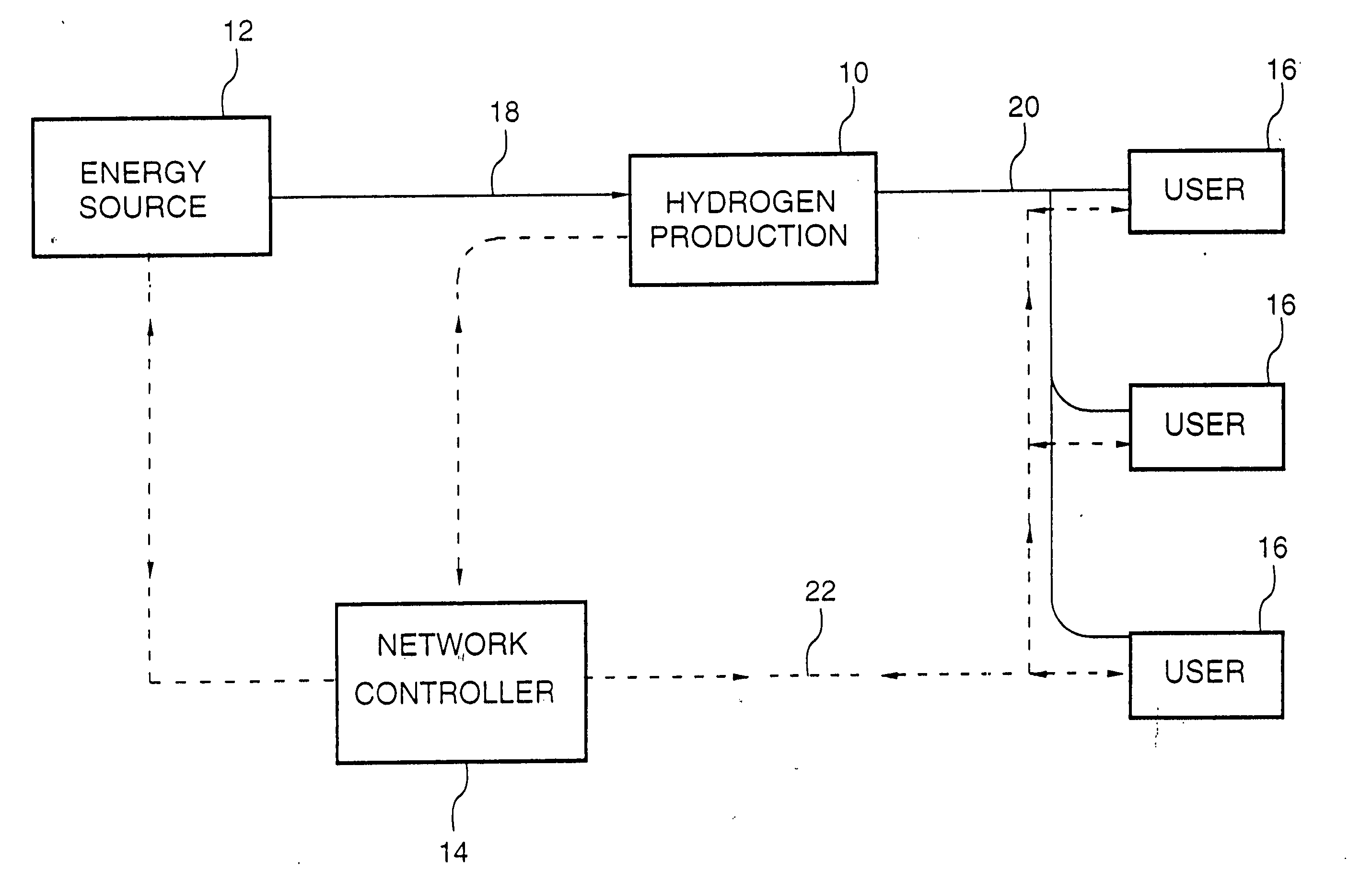
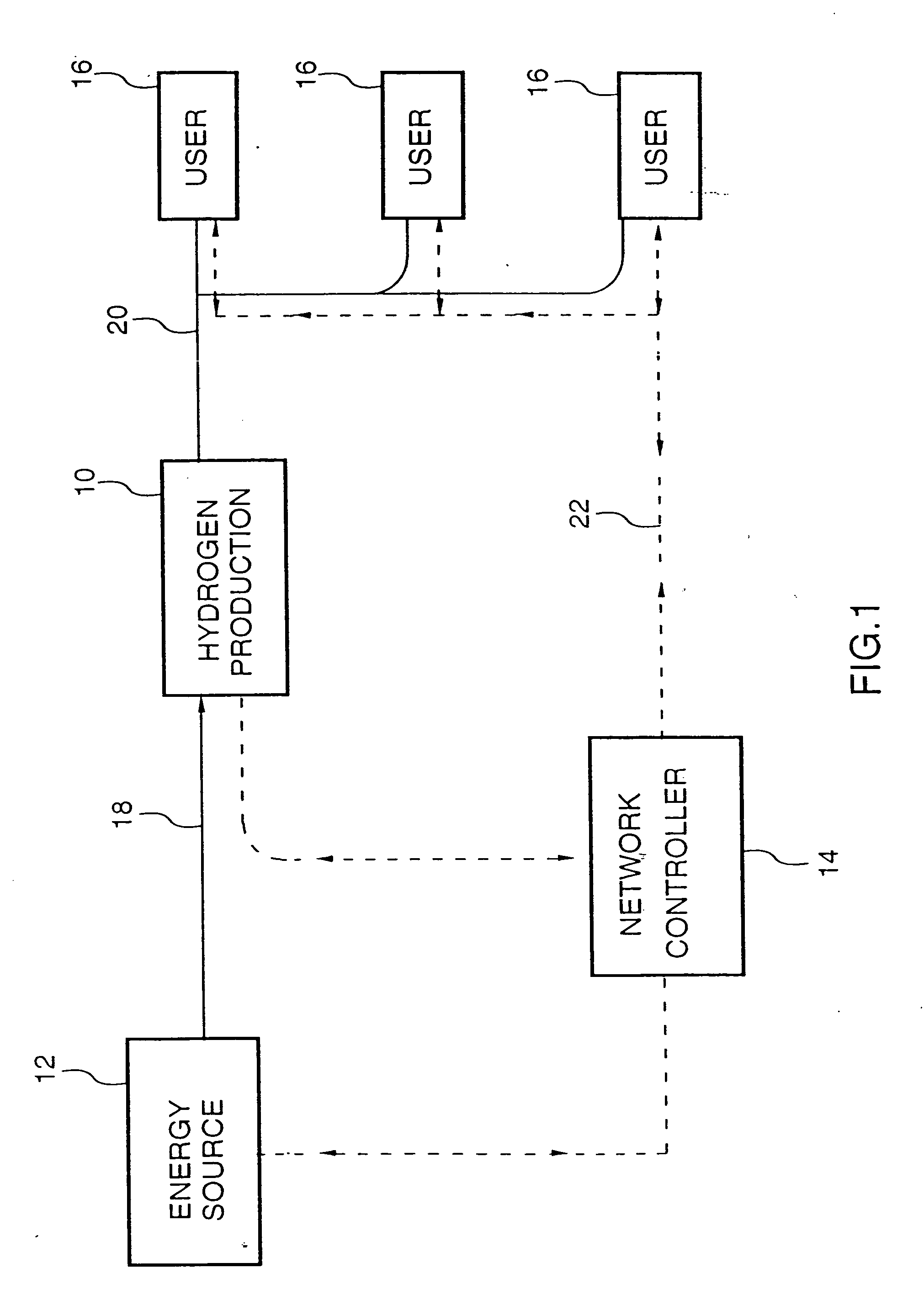
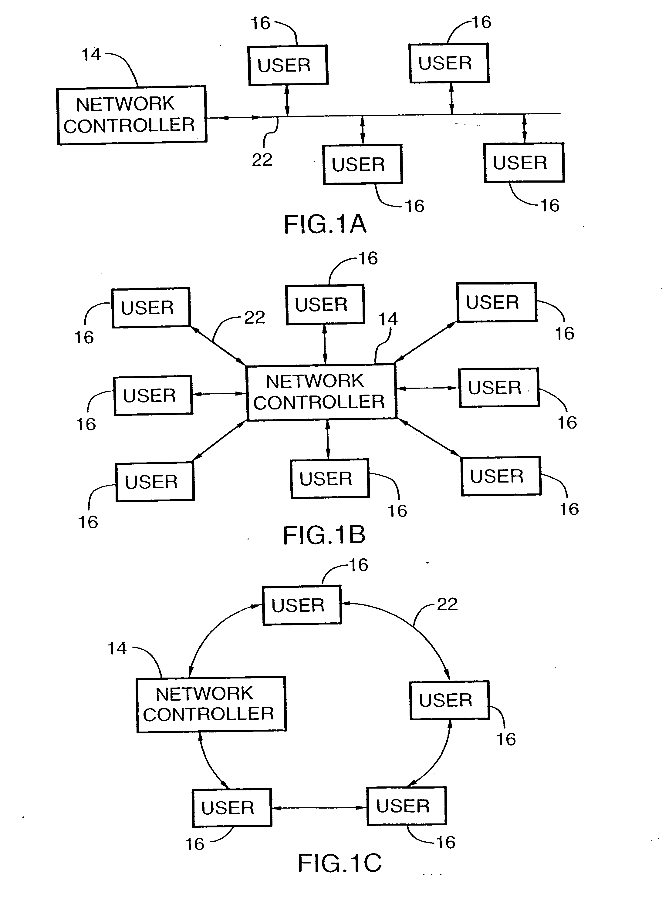
[0071] FIG. 1 represents an embodiment providing a broad aspect of the invention having a hydrogen production source 10, supplied by energy source 12 which may be an electricity generating power plant, or a natural gas, gasoline or methanol reforming plant or combinations thereof A control unit 14 and users 16 are suitably linked by hardware input and output distribution conduits 18, 20, respectively, and electrical data transmission lines 22.

[0072] Users 16 define demands for hydrogen transmitted by means of, for example (i) use of a credit card, (ii) use of a smart card, (iii) use of a voice activation system, (iv) manual activation via front panel control, (v) use of a electronic, electric, or wireless infrared data transmission system to register a hydrogen demand on the network. Upon receipt of the demand, controller 14 determines the natures of the demand with respect to the quantity of hydrogen requested, the time to deliver the hydrogen, the conditions under which to deliver...


PUM


Abstract

A hydrogen fuel supply system includes a hydrogen generator for generating hydrogen from an energy source at an outlet pressure. An outlet conduit feeds the hydrogen to a user. A controller controls the hydrogen generator to produce hydrogen at the outlet pressure. An input interface receives user demand data and activates the controller in accordance with the user demand data.

Description

[0001] This invention relates to an energy network for providing hydrogen-generated at a production site, particularly by one or more water electrolysers, for use particularly, as a fuel for vehicles or energy storage. The invention further relates to the use of hydrogen as a fuel for a fuel cell wherein hydrogen is converted into electrical energy, for combustion as an auxiliary energy source and for the generation of electricity, particularly, as part of an electrical distribution system.BACKGROUND TO THE INVENTION[0002] In planning the production capacity of a large chemical plant, for example, for methanol production or a large electricity production site, correct knowledge of expected demand of the product is critical with regard to the optimization of capital deployment and certainty of a return on investment in the large facility. Most often millions of dollars are required to finance the construction. Thus, measuring and predicting the supply and demand for the end product i...

Claims


Application Information

Patent Timeline
Patent Type & Authority Applications(United States)
IPC IPC(8): B60L11/18C01B3/00C25B15/02C25B1/04H01M8/0656
CPCB60L11/1881B60L2200/26B60L2260/54B60L2260/56C01B3/00C01B3/02C01B3/32C01B3/36C01B2203/0233C01B2203/025C01B2203/1223C01B2203/1235C01B2203/1241C01B2203/84H01M8/04216H01M8/04298H01M8/0438H01M8/04753H01M8/0612H01M8/0656H01M2250/20H01M2250/402Y02B90/12Y02E60/324Y02E60/366Y02T90/32Y02T90/34Y02E60/50B60L11/1894Y02P20/133B60L58/30B60L58/34Y02B90/10Y02E60/32Y02E60/36Y02T90/40Y02P90/60
Inventor FAIRLIE, MATTHEW J.STEWART, WILLIAM J.STUART, ANDREW T. B.THORPEDONG, CHARLIE
Owner HYDROGENICS CORP
Learn More