Eureka AIR delivers breakthrough ideas for toughest innovation challenges, trusted by R&D personnel around the world.

Dual feedback, high accuracy brake cylinder pressure control

a brake cylinder, high-accuracy technology, applied in the direction of braking systems, braking components, transportation and packaging, etc., can solve the problem of not offering the benefit of high-accuracy around a commanded pressure, and achieve the effect of reducing the valve cycle of a device, high accuracy and high accuracy

Inactive Publication Date: 2004-07-01
WESTINGHOUSE AIR BRAKE TECH CORP
View PDF16 Cites 6 Cited by
  • Summary
  • Abstract
  • Description
  • Claims
  • Application Information

AI Technical Summary

Benefits of technology

[0011] It is, therefore, one of the primary objects of the present invention to provide a dual feedback, high accuracy brake cylinder pressure control which reduces the valve cycling of a device for pressure control.
[0012] Another object of the present invention is to provide a dual feedback, high accuracy brake cylinder pressure control which increases the accuracy of the device for pressure control.
[0013] A further object of the present invention is to provide a dual feedback, high accuracy brake cylinder pressure control in which greater overall system reliability is brought about by reduced magnet valve cycles.
[0014] Still yet another object of the present invention is to provide a dual feedback, high accuracy brake cylinder pressure control which will reduce costs by reducing needed maintenance and repairs of systems utilizing the invention.

Problems solved by technology

While this loop will reduce valve cycling, it cannot offer the benefit of high accuracy around a commanded pressure.

Method used


Image

  • Dual feedback, high accuracy brake cylinder pressure control
  • Dual feedback, high accuracy brake cylinder pressure control
  • Dual feedback, high accuracy brake cylinder pressure control

Examples


Embodiment Construction

, particularly, when such description is taken in conjunction with the attached drawing figures and the appended claims.

DESCRIPTION OF THE DRAWING

[0016] The present invention will now be described by way of a particular preferred embodiment, reference being had to the accompanying drawing, wherein:

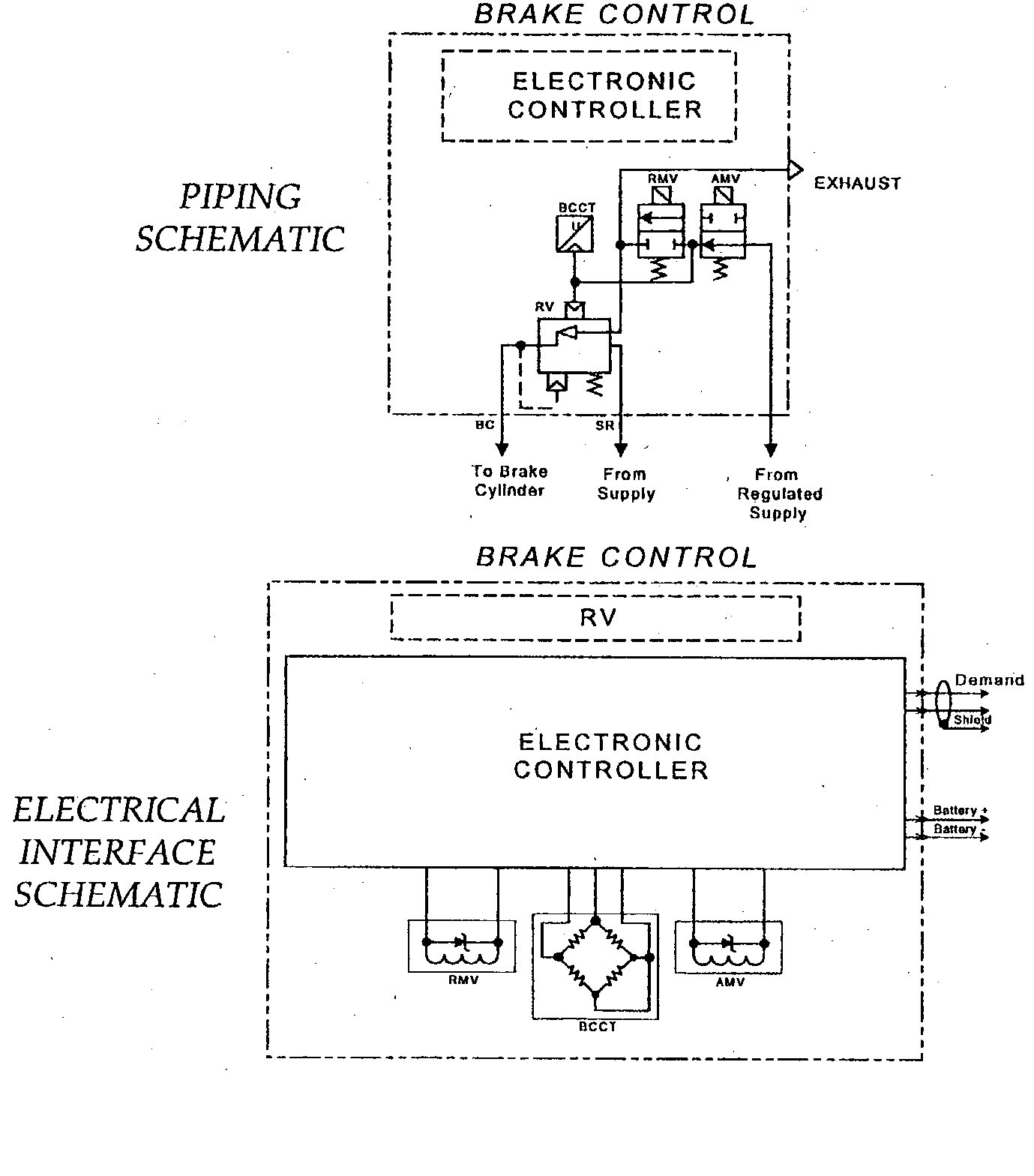
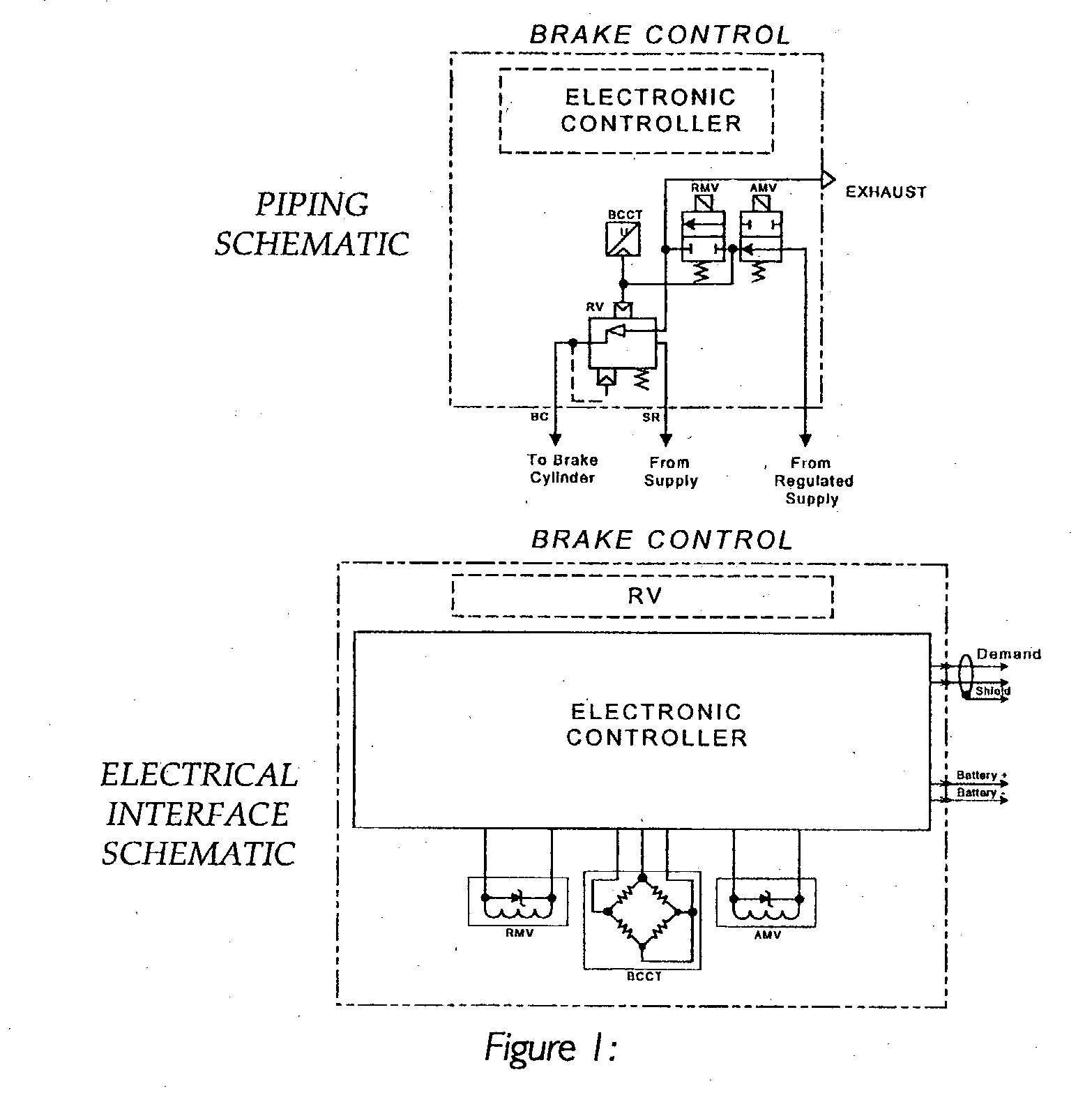
[0017] FIG. 1 is a piping drawing and electrical schematic of a prior art for electronic control of a brake cylinder pressure.

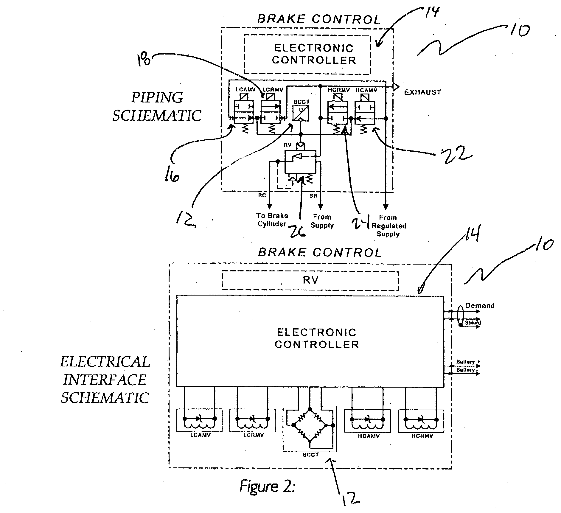
[0018] FIG. 2 is a piping drawing and electrical schematic of the preferred embodiment of the current invention for electronic control of a brake cylinder pressure.

[0019] FIG. 3 is a flow chart of a prior art approach for electronic Control of a brake cylinder pressure related to FIG. 1.

[0020] FIG. 4 is a flow chart of the presently preferred embodiment of the current invention for electronic control of a brake cylinder pressure related to FIG. 3.

[0021] FIG. 5 is a graph showing the results of a computer simulation of the pressure application and release of a low cy...


PUM


Abstract

A dual feedback, high accuracy pressure control means for railcar braking systems having an electronic control module. A transducer is electronically connected to the control module for transmitting a pressure signal to the control module. There is a source of fluid pressure with such source of fluid pressure being at least one of a supply pressure and a regulated supply pressure. At least two solenoid valves have a fluid connection to one another and to the transducer and are electronically connected to the control module for receiving at least one of an apply and hold signal. At least two solenoid valves have a fluid connection to one another and to the transducer and are electronically connected to the control module for receiving at least one of a release and hold signal. A relay valve has a fluid connection to at least two of the solenoid valves and to the transducer and to such source of fluid pressure and to a braking device. At least two of said solenoid valves have a fluid connection to such source of fluid pressure. An exhaust to atmosphere having a fluid connection to at least two of the solenoid valves and to the relay valve is provided.

Description

[0001] The present invention generally relates to pressure control devices. More particularly, the present invention relates to a dual feedback, high accuracy brake cylinder pressure control device for a railcar braking system that uses solenoid valves.[0002] Current braking systems are normally configured in one of two ways, low cycle loop control or high accuracy loop control.[0003] The system described below is covered by U.S. Pat. No. 3,398,815 and is manufactured by Westinghouse Air Brake Technologies Corporation and is sold as the RT-5. The teachings of U.S. Pat. No. 3,398,815 are incorporated herein by reference thereto.[0004] In a current braking system, a brake pressure demand signal (BPDS) is sent to the electronic controller. The electronic controller reads the control pressure from the electronic signal it receives from the brake cylinder control transducer (BCCT) The BPDS is compared to the BCCT, and if the BPDS is greater than the BCCT by a predetermined amount (i.e., ...

Claims


Application Information

Patent Timeline
IPC IPC(8): B60T8/50B60T8/34B60T13/66B60T13/68B60T15/36B61H11/00B61H11/02
CPCB60T8/5012B60T8/5081B60T13/686B60T13/665B60T13/66
Inventor MAZUR, RICHARD J.WOOD, JAMES A.
Owner WESTINGHOUSE AIR BRAKE TECH CORP
Why Eureka
Eureka Blog
Learn More